Creating my first Trim Box - Finished pics pg2

Only for Genuine FS fanatics! Taking this hobby from Real to Surreal? Or maybe just combining 4 hobbies into 1 ;)

Re: Creating a trim box - help

Postby SilverFox441 » Tue Jan 22, 2008 6:00 pm

They say a picture is worth a thousand words... hopefully this will save me some typing. :)

Image

I only showed 6 switches for clarity sake. The other six switches would be hooked up the exact same way to the 6 pins not yet used (the ROWS section). The instructions for the controller specify the simplified hookup using a ground from one of the analog inputs so that is what I drew.

Hope this helps.
Steve (Silver Fox) Daly
User avatar
SilverFox441
Major
Major
 
Posts: 1335
Joined: Sun Apr 13, 2003 12:54 am
Location: Mississauga, Ontario, Canada

Re: Creating a trim box - help

Postby SilverFox441 » Tue Jan 22, 2008 6:23 pm

I found an image from John's cockpit construction log that shows this technique in practice:

Image

The switches are different due to the different controller and purpose, but if you look at the left side of the six switches on the left side of the panel... one wire is looped from the centre contact of each switch and is in common with all the other switches. That wire is then routed (not visible, or at least untraceable in the image) to the common ground of the KE72 unit that John is using in his 'pit.

Looking closely, this might actual be a lighting function that is being hooked up... but it's the same thing in practice. :)
Steve (Silver Fox) Daly
User avatar
SilverFox441
Major
Major
 
Posts: 1335
Joined: Sun Apr 13, 2003 12:54 am
Location: Mississauga, Ontario, Canada

Re: Creating a trim box - help

Postby BS8thJaw » Tue Jan 22, 2008 7:00 pm

hmmm... lets see here.

Last night I did hook up one of my press buttons with two 18 gauge wires, I then soldered the wires to a 6 pin connector, to the two pins on the far left of the six pin, I then attached it to the controller and plugged it in to see if it worked and I got no input reply on any of the buttons.

Am I supposed to bridge one button onto both of the six pin connectors or just one of them? The way I am thinking about this is I could have 3 buttons per six pin connector... is that correct?

I think I am just thinking about this all wrong. :-/
BS8thJaw
Ground hog
Ground hog
 
Posts: 12
Joined: Fri Dec 21, 2007 8:48 pm
Location: Billings, MT

Re: Creating a trim box - help

Postby SilverFox441 » Tue Jan 22, 2008 8:09 pm

Forget about your 6 pin connectors for a moment... that will become clear once you understand the basics of what you are trying to accomplish. For example, I can't answer you question about what you hooked up because I don't know where you put the 6 pin connector when you installed it on the board. There are a bunch of ways you might have put that 6 pin on... and about half won't do any good. :)

There are two ways of hooking that controller up...

Method one is the Matrix method. In a Matrix you would hook up one side of the switch to one of the connections in the COLUMNS section and the other side of the switch gets hooked to a connection in the ROWS section. 36 switches can be hooked up this way and each pin will have 6 different connections to it from 6 separate switches.

The simplified method is what you will use for 12 switches.

Take another look at this diagram:

Image

Each switch is hooked via one wire to one pin in the COLUMNS section. The other side of the switch is hooked via one wire to any of the GND connections in the ANALOG INPUTS section.

I'll provide explicit hookup instructions to get your first switch working.

1. one wire is hooked to the first pin of a 6-pin connector.
2. the other end of that wire is hooked to one side of your chosen switch.
3. one wire is hooked to one end pin of a 3-pin connector.
4. the other end of that wire is hooked to the open connection of the switch from step 2.
5. attach the 3-pin connector so that the pin with the wire connected is closest to the edge of the board at ANALOG INPUT 8.
6. attach you 6-pin connector along the COLUMNS section so that the pin with the wire attached is at position 1.

For hooking up your other switches the connection to ANALOG INPUT 8 will be common to them all. The next five switches you hook up will have one side hooked to the remaining unused pins on that first 6-pin connector. The second bank of 6 switches will mirror the first six with the exception that the 6-pin connector will be hooked to the ROWS section instead of COLUMNS.

Try that.
Steve (Silver Fox) Daly
User avatar
SilverFox441
Major
Major
 
Posts: 1335
Joined: Sun Apr 13, 2003 12:54 am
Location: Mississauga, Ontario, Canada

Re: Creating a trim box - help

Postby JBaymore » Tue Jan 22, 2008 8:20 pm

Image above is the rear of my anti-ice panel.

BS8thJaw, if you happened to use the push on / push off buttons to test... that may be one problem.  They will not work with that controoler without some external circuitry.  Use only MOMENTARY buttons.

You need only TWO wires from the controller board to each switch.  One is the "hot" lead, and the other is the ground lead.  The button's function is to "short" the hot lead to the ground.... thereby telling the controller a button was pressed.

You can "share" all of the ground leads from switch to switch........ saving on a lot of wires going back to the controller.  Then only ONE main ground lead that is daisy-chain connected to one pole of each button runs back to the controller.  For six switches, only SEVEN leads...... six hot leads (one on each switch) and one ground lead.

best,

....................john
Image ImageIntel i7 960 quad 3.2G LGA 1366, Asus P6X58D Premium, 750W Corsair, 6 gig 1600 DDR3, Spinpoint 1TB 720
User avatar
JBaymore
Global Moderator
Global Moderator
 
Posts: 10020
Joined: Sat May 24, 2003 9:15 am
Location: New Hampshire

Re: Creating a trim box - help

Postby BS8thJaw » Wed Jan 23, 2008 12:06 am

Alright, after talking to the guy at radio shack when I went back to buy some turn knobs I now understand the philosophy behind this entire project. With that, I was able to accelerate with great speed and finished my box in no time at all. Had a little trouble soldering but thats only because my solder gun sucks terribly...


Anyway, here are the pictures, I shrunk them to 1280x960 so hopefully they aren't too large. Enjoy :)
|
|
|
|
|
|
|
|
|
|
|
|
|
|
|
|
|
|
|
|
|
|
|
|
|
|
|
|
|
|
|
|
|

The workstation, before I began :D you can see the box on the lower left corner of the pic, I forgot to take a picture of the box alone before anything went inside it.
http://www.blacksheep8th.com/JJR%20004.jpg
the mounting of the board, I used 4 very tiny screws and secured it to the bottom block inside the box. The block was meant to raise the chip to the correct height so I could make the hole to connect the wire.
http://www.blacksheep8th.com/JJR%20002.jpg
http://www.blacksheep8th.com/JJR%20001.jpg
The lid with the pre-aligned holes drilled
http://www.blacksheep8th.com/JJR%20005.jpg
The lid after the potentiometers were added. Radio Shack was out of the smaller potentiometers with the smaller shafts so I got stuck with these - no problem tho, look further down to see my solution.
http://www.blacksheep8th.com/JJR%20006.jpg
The alignment of the three buttons I added, I realized that adding the full 12 was a bit unrealistic at this point, although I might add more in the future.
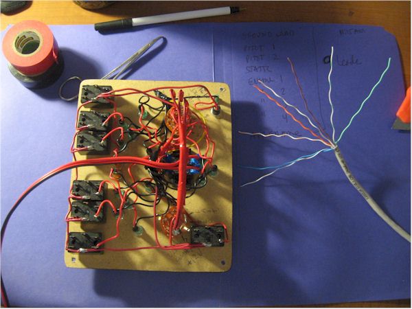
http://www.blacksheep8th.com/JJR%20008.jpg
The wonderful mess of wires inside the box before sealing her up. Aint it beautiful?
http://www.blacksheep8th.com/JJR%20007.jpg
The box, finished and sealed with the famous Hot Glue Gun, I did this so it would be easy to take the cover off in the future in case I want to add something to it. My solution for the tall potentiometers was to take a hack saw and saw them off just slightly higher than my knobs, after that the knobs mounted rather easily.
http://www.blacksheep8th.com/JJR%20009.jpg

Linked images changed to URLs  -jcb

I think I did fairly well for my first build. It only took me two days to put it together so thats not bad. I soldered all points together and then used the hot glue gun to add a protective layer on them to keep them from accidentally touching inside the box. All points have been volt tested to assure all points are getting the voltage required. The other thing I might add is the hole that I put in the front of my box for my cord was perfect - the cool thing is, the wood I used was just thick enough to provide just the right amount of space between the board inside the box and it connects snuggly, this will keep anything from pulling down from the weight of the cord so it turned out nicely. The wood I chose was some old trim board we had laying around our house, actually the finish on the board was rather nice, although with the addition of my brownish wood glue to hold it together it kind of ruined the effect.

Oh well its not like it has to look all that pretty, as long as it does its job correctly ;)

Thank you one and all for the help and assistance, it was much appreciated and I would not have gotten through this on my own.

S~ To everyone.
Last edited by JBaymore on Thu Jan 24, 2008 9:15 pm, edited 1 time in total.
BS8thJaw
Ground hog
Ground hog
 
Posts: 12
Joined: Fri Dec 21, 2007 8:48 pm
Location: Billings, MT

Re: Creating my first Trim Box - Finished pics pg2

Postby SilverFox441 » Wed Jan 23, 2008 1:41 am

I hope you realize that exposure to the cockpit building disease can't be cured?

You will suffer bouts of infection forever and feel a strong urge to build or modify stuff for the rest of time.

;)

*insert evil laugh here*

Glad it worked out, have fun with the new toy.
Last edited by SilverFox441 on Wed Jan 23, 2008 1:41 am, edited 1 time in total.
Steve (Silver Fox) Daly
User avatar
SilverFox441
Major
Major
 
Posts: 1335
Joined: Sun Apr 13, 2003 12:54 am
Location: Mississauga, Ontario, Canada

Re: Creating my first Trim Box - Finished pics pg2

Postby beaky » Wed Jan 23, 2008 1:37 pm

Well done... but take heed: fly the sim now, while you can!!

For once the 'pit-building disease takes root, you will never fly again.... building... always buiiiiilllldiiing....never flyyyyiiinnnggg..... woooooooo... (fade out w/reverb and rattling chains)


:D
Image
User avatar
beaky
Global Moderator
Global Moderator
 
Posts: 12877
Joined: Thu Dec 16, 2004 8:00 am
Location: Shenandoah, PA USA

Re: Creating my first Trim Box - Finished pics pg2

Postby Padser » Mon Feb 11, 2008 6:39 pm

Yes, this way madness lies...  ;)

Good to see a fellow IL-2-er in here Jaw and your switch box is exactly how I started out.  Some of the first faltering steps I took on the journey to arriving at the device I now can't imagine flying with out can be found here: [url]http://forums.ubi.com/eve/forums/a/tpc/f/26310365/m/9831081034/p/1
[/url]
I fly on Hyperlobby as 234Sqn_Pads these days - look out for me, I'd be happy to help. Or drop me a line on my squad forum - easiest to access it via the web site: http://www.234squad.org.uk

TTFN

Pads
Padser
2nd Lieutenant
2nd Lieutenant
 
Posts: 241
Joined: Wed May 21, 2003 8:24 am

Re: Creating my first Trim Box - Finished pics pg2

Postby BS8thJaw » Wed Feb 13, 2008 1:36 pm

wow... that is all I can say is wow. That is amazing - yet this gives me more ambition to do even more. The chair is very nice, I would be interested in seeing more detail on how you did that chair. Btw, how awkward is it to have a joystick centered on your body? I usually fly with mine off to the side and its respectably comfortable - I did however have a chance to go to the flight sim center at the Mall of America in Minnesota recently where I flew one of their "simpits", so to speak, they were pretty awesome; they had center mounted joysticks in them, after a hour of flight however I found that my wrist was feeling a little awkward from the extreme angle I had to put it at to  use the joystick; Any input on this matter?

I am actually now planning to create a separate box for separate engine control, instead of having to buy a CH throttle quad which would cost me like 70-100 bucks or more. The idea I had was to make a simple box, like I did before and have it control only the prop pitch. Of course I would add more to it, such as more buttons and whatnot.

Actually now that I think of it, I should redo my trim box design into a grand master design, a bigger box, with maybe even more than one controller on the inside possibly connected by using a USB hub? On that box I could add several buttons, switches, potentiometers and such until my hearts content. Of course, then it comes down to how much room I have for this thing and if it will fit on my desk... lol.

This idea really makes me wish that IL2 supported separate engine control (separate throttles for each engine) instead of all on the same one. The possibilities with this controller is pretty much endless.
BS8thJaw
Ground hog
Ground hog
 
Posts: 12
Joined: Fri Dec 21, 2007 8:48 pm
Location: Billings, MT

Previous

Return to Home Cockpits and Setups

Who is online

Users browsing this forum: No registered users and 323 guests