OK- here's a quick and unrefined tutorial
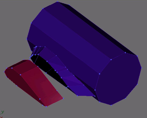
The set up is similar to Ender Baron's screen shot. I've gone into the properties and turned on the vertice tics so it's easier to see what's going on. I made it so there are different numbers of vertices on the edge of the wing and on the edge of the fuselage.
First grab the line tool, and then create a simple closed spline that has the number of vertices that you want to have in your connector patch. In this example I'll want nine vertices. It's important that you make this spline in an open area on the viewport, and not on top of other shapes.
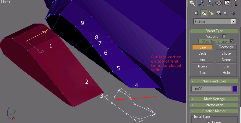
Answer yes when it ask if you want a closed spline. With the spline selected, select edit mesh modifier or just convert the spline to an editable mesh.

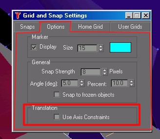
Right click on the 3d snap button to bring up the grid and snap settings - under options make sure the translation use axis constraints is UNCHECKED
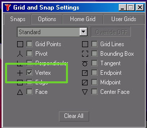
under snaps just select vertice - have everything else unchecked
Now select the connection patch polygon and get into edit mesh, vertice level, with 3d snap ON (hitting the S key will toggle the 3d snap tool on and off) and then click and drag the vertices to the different vertices on the two shapes you want to connect.
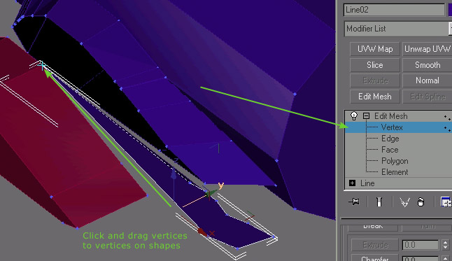
I changed the color of the polygon so it'd be easier to tell apart from the other shapes. Work your way around till all the vertices have been snapped into place.
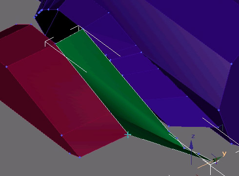
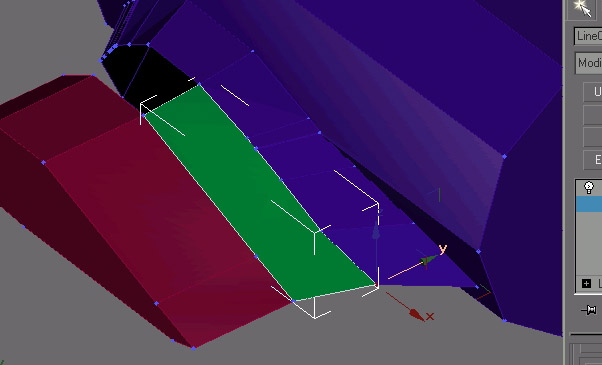
You should end up with something that looks like this
Then it's just a matter of picking either the wing or the fuselage and with an edit mesh modifier on, select attach and then click on your connection polygon and you set.
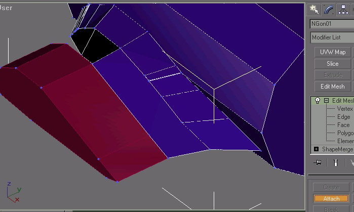
Then you would repeat the process until you had all the patches you needed to complete the connection. I usually would have 3 or four, depending on how curvered the bottom of the wing is.
Hope this helps. Gotta go pack.


 [img]http://www.sierrahotel.or
 I used Mr. Preece's advice and did the stuborn thing. Only problem is, its gonna take me another two hours to do the tail! But, since I was a bimbo, I'm getting my just desserts.