Today I got some time to spend on continuing work on the enclosure. The roof of the "cockpit" was next on the list of stuff to complete because the overhead panel will house a lot of the main power supply functions of the whole project. I have to attend to that stuff soon so that I can get all the wiring stuff started.
Photo #1

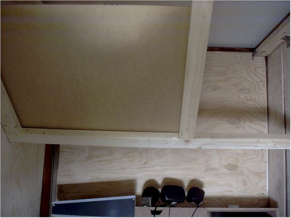
Photo #1 above shows the angle of the roof and overhead panel drawn on the side wall of the enclosure. The cockpit design was planned from the start to house a wide throw lcd projector in the empty space above the roof and overhead panel. The angle and spacing of the roof itself is set so that the projector unit will have a free "view" of the "out the windscreen" wall where it will project the pilot's main exterior view.
All the overhead wood (2" x 3"-s) is attached using screws and metal joist hanging brackets and angle brackets and such. No glue used here....... I may want to move this someday. The roof over the pilot's seat will be faced with 1/4" MDF and will actually be an "access hatch" when it is removed to get at the overhead area.
Photo #2
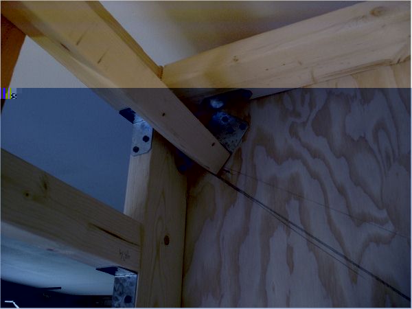
Photo #2 above shows the other end of the slanting cockpit roof near the top of the whole enclosure. There is enough space above this so that a lcd projector can be mounted up there (with cooling fans). The throw to the screen area from the lens will be exactly five feet.
Photo #3

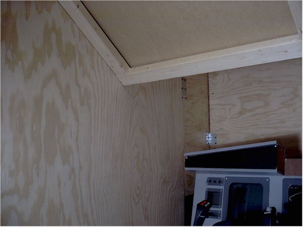
Photo #3 above shows the wood support along the encluosure wall that will support the roof over the pilot's head. The "roofing" will be mounted on the top of this framing in this area, while the overhead panel will be mounted on the bottom of the wood framing. This will give a sense of depth to the roof structure.
Photo #4
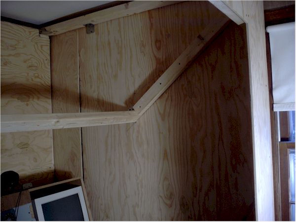
Photo #4 above shows the wood framing along the opposite end wall which is over the center pedestal area. This side is where the actual main overhead panel will be located. The framing wood is placed vertically here because I want the margin along this wall to be narrower than on the other walls.
Photo #5
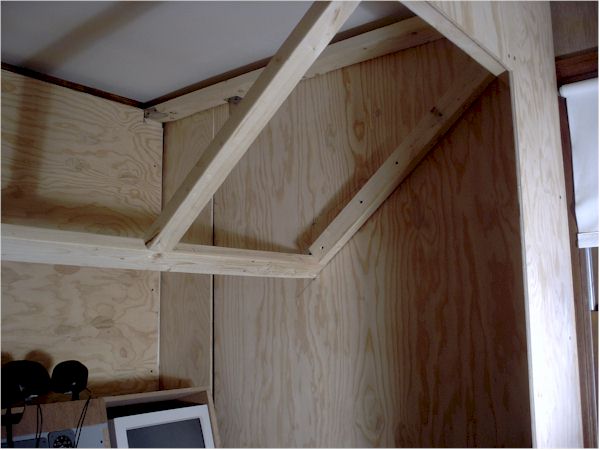
Photo #5 above shows the framing around the main overhead panel. It is sized so that three bays of 7 1/4" wide panels can be mounted there. All of my panels are designed around the width of the Goflight avionics units..... so I am keeping this constant here too. That will allow me to mount a Goflight unit here if I decide to.
Photo #6
In photo #6 above you can see the location of the roof over the pilot's head. This panel will be easily pushed up to remove it. It will get an "eyebrow" window on the left, a map light unit, an air circulation unit, and a small panel for the landing light switches along the bottom front.
The spacing for the height of this roof area was studied from real aircraft as well as my own body ergonomics. I also took measurements in various cars.
In photos #7 and #8 below you can get some sense of the general layout of the roof structure relative to the main instrument panel area.....although the MIP is all torn up at the moment. I have also tightened up a fre enclosure panels in the background .... and another monitor for the engine management systrem is now in place too.
Photo #7
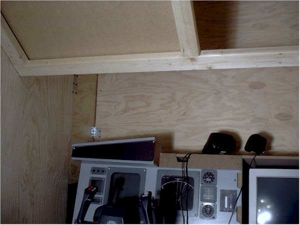
Photo #8
Feels good to get back to more work on this project ;)
More coming soon.
best,
.......................john
 Intel i7 960 quad 3.2G LGA 1366, Asus P6X58D Premium, 750W Corsair, 6 gig 1600 DDR3, Spinpoint 1TB 720