Cockpit Construction Continued (Part 5)

Only for Genuine FS fanatics! Taking this hobby from Real to Surreal? Or maybe just combining 4 hobbies into 1 ;)

Cockpit Construction Continued (Part 5)

Postby JBaymore » Sun Apr 04, 2004 5:48 pm

Renamed this topic to fit the ongoing updates format of the CCC (Part x) stuff that I started


Custom Instrument Panels


As I am laying out the "generic" simpit I'm building..... I have found that I can custom make the various panels for many of the flight controls.... since I am not "tied" to re-creating an exact duplicate of some real aircraft.
Last edited by JBaymore on Sat Apr 17, 2004 7:40 pm, edited 1 time in total.
Image ImageIntel i7 960 quad 3.2G LGA 1366, Asus P6X58D Premium, 750W Corsair, 6 gig 1600 DDR3, Spinpoint 1TB 720
User avatar
JBaymore
Global Moderator
Global Moderator
 
Posts: 10020
Joined: Sat May 24, 2003 9:15 am
Location: New Hampshire

Re: Cockpit Construction Continued (Part 5)

Postby P-40_Warhawk » Fri Apr 23, 2004 10:15 am

This series is great! Keep these coming!
Some say my pinky toe was replaced with a fountain pen, and that I love to ride on nuclear bombs with a saddle. All I know is.... I'm called THE STIG!!!!
User avatar
P-40_Warhawk
2nd Lieutenant
2nd Lieutenant
 
Posts: 265
Joined: Mon Apr 07, 2003 1:23 pm
Location: Savona New York

Re: Cockpit Construction Continued (Part 5)

Postby JBaymore » Mon Apr 26, 2004 10:32 pm

P40_Warhawk,

Thanks.

I plan on posting a lot of the stuff I am doing.

I hope others will follow this idea and share photos of their ideas.  The more the merrier.  ;D

best,

.................john
Image ImageIntel i7 960 quad 3.2G LGA 1366, Asus P6X58D Premium, 750W Corsair, 6 gig 1600 DDR3, Spinpoint 1TB 720
User avatar
JBaymore
Global Moderator
Global Moderator
 
Posts: 10020
Joined: Sat May 24, 2003 9:15 am
Location: New Hampshire

Re: Cockpit Construction Continued (Part 5)

Postby P-40_Warhawk » Tue Apr 27, 2004 10:35 am

I will prob. copy youre design when i make my simpit. (I have no electrical expertise at all.) Can you post a general pic of how it looks with all the components that are made in place?
Some say my pinky toe was replaced with a fountain pen, and that I love to ride on nuclear bombs with a saddle. All I know is.... I'm called THE STIG!!!!
User avatar
P-40_Warhawk
2nd Lieutenant
2nd Lieutenant
 
Posts: 265
Joined: Mon Apr 07, 2003 1:23 pm
Location: Savona New York

Re: Cockpit Construction Continued (Part 5)

Postby P-40_Warhawk » Tue Apr 27, 2004 10:39 am

BTW-can you put up some diagrams of wiring? (like the status panels)
Some say my pinky toe was replaced with a fountain pen, and that I love to ride on nuclear bombs with a saddle. All I know is.... I'm called THE STIG!!!!
User avatar
P-40_Warhawk
2nd Lieutenant
2nd Lieutenant
 
Posts: 265
Joined: Mon Apr 07, 2003 1:23 pm
Location: Savona New York

Re: Cockpit Construction Continued (Part 5)

Postby JBaymore » Sat Aug 21, 2004 1:48 pm

Here are a couple more of the designs for the custom panels that will populate the center console pedestal in my simpit.

This panel below is mainly for the rudder trim function..... but it also houses a couple of other functions.  The first image is the panel facing itself.  It will get switches, led's, and rotary potentiometers for the control circuitry.  

The dark grey rectangles on the left of the main panel facing are the places that a pair of curved 1/4" MDF "shields" will be mounted that project outward at a 90 degree angle from the panel facing.  This is to prevent accidental mis-adjustments of this control.

The rectalinear white box above all the other stuff is for the actual rudder trim gauge readout.  This space will simply be cut out to make an opening.  Then a small piece of 1/8" MDF will be cut to make a "frame" around the opening with about a 1/4" wide band of material framing the opening....to make it look more like a real gauge assembly.


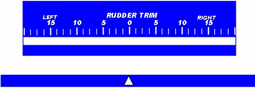
The second image below the panel facing is the "gauge" that will go behind the rectalinear cutout in the panel facing.   It will be printed via an inkjet printer on transparent film so that light will come thru it. That's why the nice "boeing Blue"  ;).   The upper part with the numbers and labels will be mounted between the "frame" and the main panel structure like the glass in a real gauge.

The little strip of blue with the white "pointer" will be mounted behind the first image so that it is alligned to the small clear strip along the bottom of the numbers and calibrations.  This will be able to slide back and forth and move the pointer along the calibration.   So you'll have a little white moving pointer in the field of blue.

This thin strip will be attached to the potentiometer the way old radio tuning dials were configured.... with a string system to move them.  As the rudder trim potentiometer is turned........ the string wraps or unwraps and hence moves the pointer on the dial face back and forth.

Mechanical pictures of the "tuning" stuff later in another thread.

SO...... some more stuff for ideas or copying for ya'.

best,

...................john


Image


Image
Image ImageIntel i7 960 quad 3.2G LGA 1366, Asus P6X58D Premium, 750W Corsair, 6 gig 1600 DDR3, Spinpoint 1TB 720
User avatar
JBaymore
Global Moderator
Global Moderator
 
Posts: 10020
Joined: Sat May 24, 2003 9:15 am
Location: New Hampshire

Re: Cockpit Construction Continued (Part 5)

Postby JBaymore » Sat Aug 21, 2004 7:57 pm

Hi gang.

Here are yet some more of the instrument panel facings for the controls in my simpit.

The first one below is for the main controls for the various general cockpit lighting.
Last edited by JBaymore on Sat Aug 21, 2004 8:10 pm, edited 1 time in total.
Image ImageIntel i7 960 quad 3.2G LGA 1366, Asus P6X58D Premium, 750W Corsair, 6 gig 1600 DDR3, Spinpoint 1TB 720
User avatar
JBaymore
Global Moderator
Global Moderator
 
Posts: 10020
Joined: Sat May 24, 2003 9:15 am
Location: New Hampshire


Return to Home Cockpits and Setups

Who is online

Users browsing this forum: No registered users and 380 guests