Landing light problem in Chris Evans Delta A321 NEO

FSX including FSX Steam version.

Landing light problem in Chris Evans Delta A321 NEO

Postby Evan Popchock » Thu Feb 06, 2025 4:35 pm

I recently did a night flight from New York to West Palm Beach in the Delta A321 NEO by Chris Evans, and I have noticed that the landing lights don't illuminate the runway (upon switching to outside view of the aircraft, it's visible that the landing light only illuminates immediately in front of the aircraft (as illustrated in the below screenshot). I also have provided a screenshot of the "electrical" section of the aircraft cfg. so hopefully someone could easily point out any discrepancies that may exist that could be causing this landing light issue

https://simviation.com/phpupload/uploads/1738927405.png

https://simviation.com/phpupload/uploads/1738893901.png
Evan Popchock
2nd Lieutenant
2nd Lieutenant
 
Posts: 209
Joined: Tue Dec 28, 2010 2:12 am
Location: Pittsburgh, Pennsylvania

Re: Landing light problem in Chris Evans Delta A321 NEO

Postby serbir » Sun Feb 23, 2025 9:06 am

The problem is in the FSX exterior model file A321 NEO.mdl, the landing lights are pointing too low.
Moreover the extra landing lights at the wings' roots have no effect since the model's author used a light
effect file which probably most of the users don't have: fx_landing_light_Dante_A320.fx

You can see the influence of these extra landing light in the FSX default A321 model.

I've fixed the problem, as seen in the picture below, but I'm not sure I can publish it since the model is copyrighted
by Project Airbus.
Perhaps the site's administrator can give me advice on this matter.

The CFM model suffers from the same problem and I've fixed it as well.

Image
serbir
Ground hog
Ground hog
 
Posts: 15
Joined: Tue Apr 25, 2023 4:24 am

Re: Landing light problem in Chris Evans Delta A321 NEO

Postby pete » Mon Feb 24, 2025 1:48 am

I've fixed the problem, as seen in the picture below, but I'm not sure I can publish it since the model is copyrighted
by Project Airbus.


You can post any fix or image no problem!
Simplicity is the ultimate sophistication. – Leonardo da Vinci
User avatar
pete
Administrator
Administrator
 
Posts: 10235
Joined: Mon Jan 01, 2001 2:01 am
Location: Cloud Cuckoo Land

Re: Landing light problem in Chris Evans Delta A321 NEO

Postby ReggieC » Mon Feb 24, 2025 5:27 pm

Would you mind posting how you made them work correctly please?
ReggieC
Ground hog
Ground hog
 
Posts: 15
Joined: Mon Dec 07, 2015 7:17 am

Re: Landing light problem in Chris Evans Delta A321 NEO

Postby serbir » Wed Feb 26, 2025 5:25 pm

Sorry for not answering earlier.
As you probably know light effects can be defined in the aircraft.cfg file of the airplane in question under the [lights] tag.
The FSX SDK tells us which kind of lights can be defined as shown in the picture below:

Image

This is fine as long as the lights are positioned at static locations relative to the aircraft's body, but what happens if the
airplane has a retractable landing gear and we carefully position the lights where we think there should be?
Well I did this for the sake of the example and added a sixth light (light.5), of the landing kind, to the A321 NEO as follows:

[lights]
light.0=3, -77.90, -0.15, 4.80, fx_navwhih
light.1=2, -77.90, 0.15, 4.80, fx_strobeh
light.2=1, 6.80, 0.00, -5.80, fx_beaconh
light.3=1, 3.83, 0.00, 8.47, fx_beaconh
light.4=4, 47.0, 0.00, 4.1, fx_vclighth
light.5=5, 51.0, 0.00, -8.1, fx_landing

The result, after retracting the nose landing gear, is a hanging light spot beneath the cockpit at a constant distance from the
fuselage flying along with the airplane as long as the landing light switch is on:

Image

In these cases aircraft designers attach these effects to the corresponding moving parts in the model so they move together when
a trigger, such as pressing the G key, initiates an animation such as a landing gear retraction.

So basically we need to tweak the aircraft model in order to fix the problem.

For this purpose I use a freely available tool called ModelConvertX (MCX) which has been around for more than 10 years.
The original intention of the tool was to preserve the work of freeware objects designers, who created plenty of
houses, bridges, trees, cars, airplanes and so forth models for FS9, by converting them to FSX compatible
format so they can be migrated to the, then, new simulator.

MCX allows, among other things, to visualize and change models objects and convert them between formats.
The tool is updated constantly. These days the author is working mostly on FSX to MSFS 2020/2024 conversions.
MCX can be found here: https://www.scenerydesign.org/modelconverterx/

The next picture is what we see after opening the aircraft model in MCX with the landing gear opened

Image

Take a look a the blue,red and green lines around the gear strout, they can be better visualized if the model is
rendered as a wire frame:

Image

Image

The small red squares represent the position of the effect relative to the aircaft's body parts in 3D space.
Each such red square is the center of a kind of orthogonal 3D space coordinate system represented by the
red, blue and green lines.
The angular disposition of this coordinate system represents the rotation of the effect relative to the longitudinal,
lateral and vertical coordinates of the airplane itself.

The direction in which the 'light' particles of the light effect are emitted goes along the green axis and if we imagine an arrow,
then the red square is its head and the end of the green axis its tail.

If we follow the green line I marked in the picture above as the landing light effect, we can see it meets the ground very
close to the front landing gear wheels. This is why the landing light illuminates just a small triangle on the ground.

Don't ask me how I figured out which one of those many red dots on the front landing gear strout is the landing light effect, I leave
this to you as an exercise should you decide to play around with MCX.

So from this point on it is just a tedious trial and error process composed of little adjustements to the landing effect's position
and angle of incidence and testing the result in the sim until we are satisfied with the results.

This is what I ended up after several iterations

Image

In the same fashion I adjusted the extra landing lights at each side of the airplane located at the wing's root.
These lights are also attached to retracting lamps.
The combined effect of all landing light sources can be seen in the 'After' picture of my previous post.

I'll release the revised PW and CFM models shortly.

Well, I believe I've answered your question
Cheers
serbir
Ground hog
Ground hog
 
Posts: 15
Joined: Tue Apr 25, 2023 4:24 am

Re: Landing light problem in Chris Evans Delta A321 NEO

Postby brownsunny148 » Tue Aug 12, 2025 9:39 pm

This is a very in-depth tutorial! I saw you mention 'adjusting the position and angle' of the lights. Can you share more about how you determined the exact coordinates of the light effect in MCX? Was it just trial and error, or is there a method that helped you figure it out faster?
Flying is more than a sport,poor bunny it's a way of life.
brownsunny148
Ground hog
Ground hog
 
Posts: 1
Joined: Mon Dec 04, 2023 11:59 pm

Re: Landing light problem in Chris Evans Delta A321 NEO

Postby serbir » Fri Aug 15, 2025 8:10 am

I admit that in this particular case I've used the trial and error approach.
Nevertheless I'll explain how it can be done using a more methodical procedure.

It is important to understand that MCX is not a fully fledged graphical 3D modelling tool and as such
it has limitations and doesn't provide tools to acomplish simple tasks such as measuring distances for example.
(as far as I am aware of)

I will also assume that you know how to navigate your way inside MCX, I definetly do not want this answer
to became a full MCX tutorial, so if a refer to a certain menu or icon you should select or press, please
search the internet for tutorials on MCX, there are plenty of them out there.

The explanation will be done on the same model as in the previous posts.
So, let's get started:
a. Open MCX
b. Load the exterior *.mdl file of the model in question
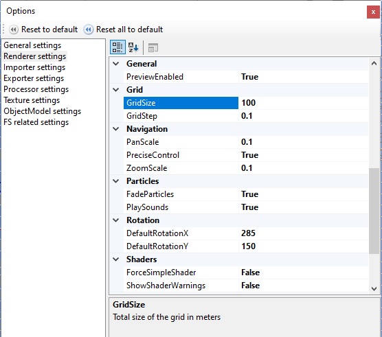
c. Open the Options Menu and set the Grid and Navigation values to suite your needs
The following is a good starting point:
Image


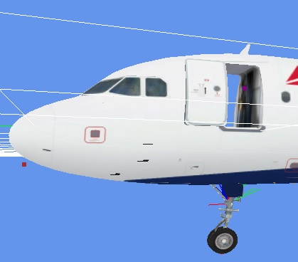
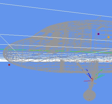
d. Select the wire frame mode of viewing the model
e. Press the 'Camera view mode' selection arrow and choose 'Left'
f. Move the animation arrow bar completely to the right so the landing gear is open
and in the compressed position which corresponds to an airplane sitting on the ground

The following is a detail of the area of interest:
Image

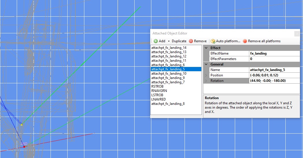
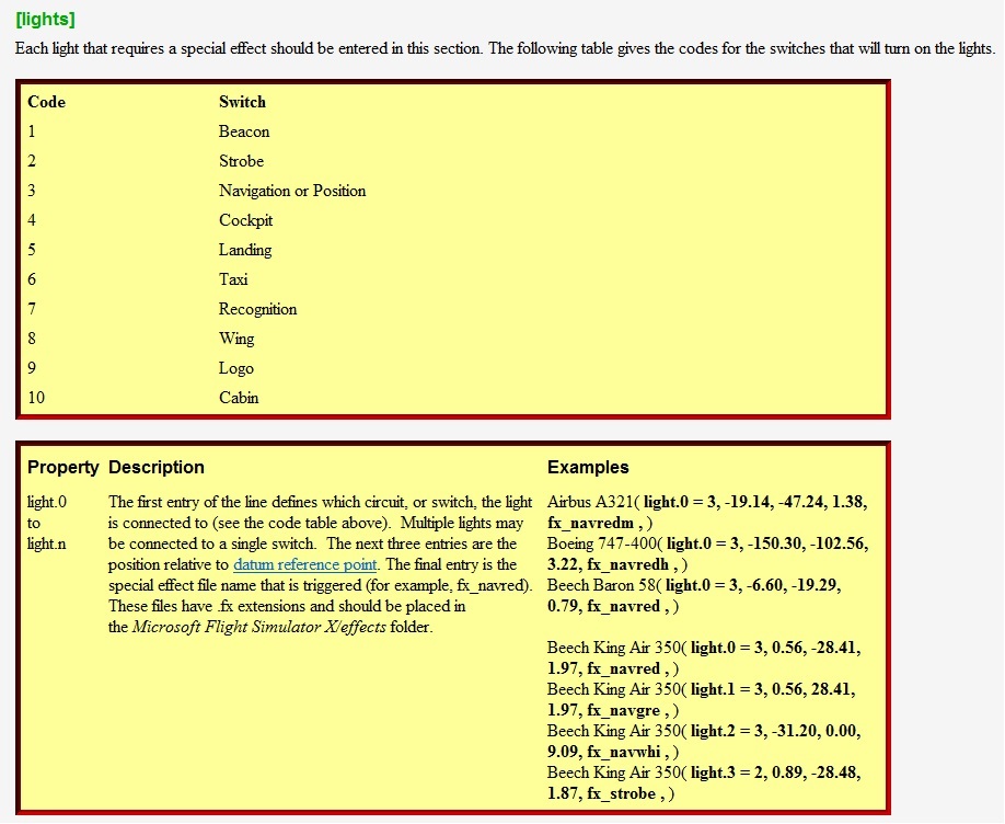
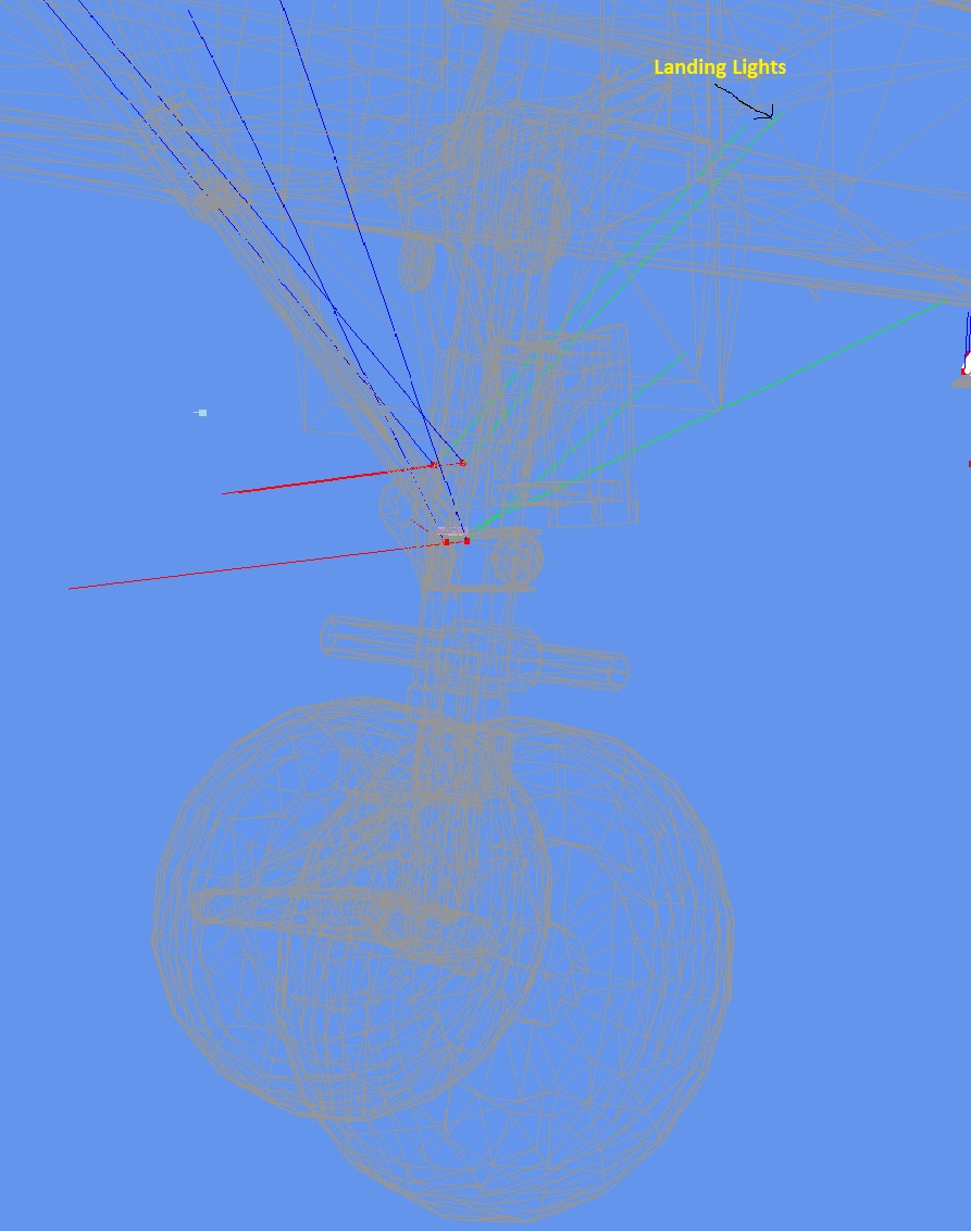
I've also opened the 'Attached Object Editor' window and selected the 'attachpt_fx_landing_5'
item which I know for sure is a landing light.

Note that when an item is selected its red dot became yellow so its easier to identify it amongst
the other attached effects.
In this particular model there are 10 attached light effects where four of them are landing lights
and the others are taxi lights.

As can be seen in the 'Attached Object Editor' there are some parameters on the right hand side that we can play with,
the most interesting being the Position and Rotation.

Unless you find the attach point is way off place there is no need to tamper with the Position parameters.
On the other hand the rotation in the vertical axis (Z) seems too steep, a clear candidate for improvement.
By the way the Z,Y and X rotations correspond to the vertical, lateral and longitudinal axes.

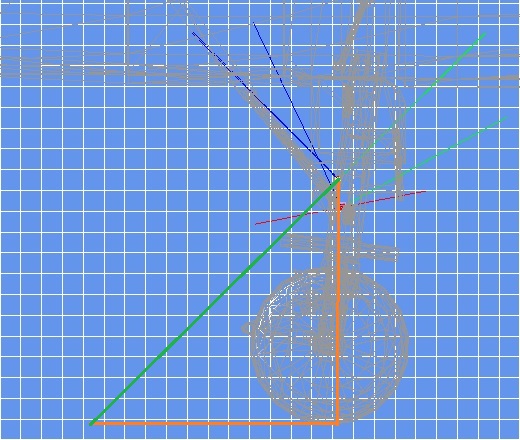
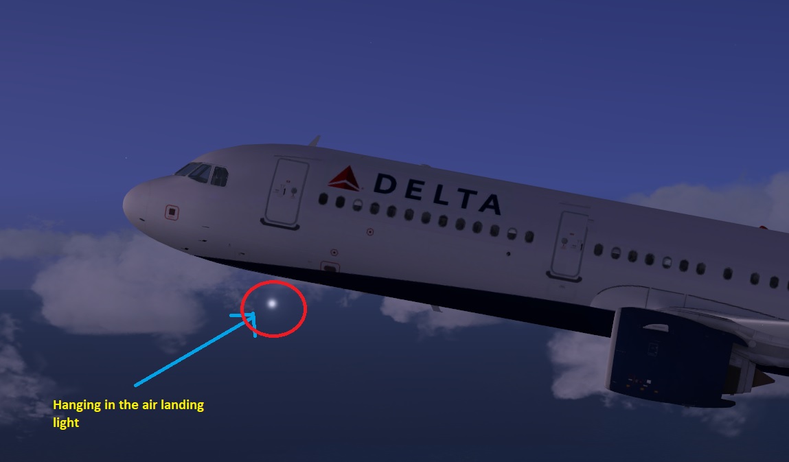
I want to know the angle of incidence of the landing light beam represented by the upper green trace.
For this matter I'll contruct a right angled triangle where the green line is its hypotenuse, as seen in the
following image:
Image

I can compute the angle of incidence of the light beam (the angle between the hypotenuse and base sides of
the triangle) if I know its tangent, which by the way is the cotient of the triangle's height by its base. as we remember
from our trigo classes.

Now comes the clumsy part: since MCX does not have a distance measuring tool, we need to count
grid cells.

As can be seen they are both approximatly the same 7 units in length (the base is a bit longer but I'll disregard this detail)
so the angle's tangent is equal to 7/7 = 1.
Now using our favorite scientific calculator we find that the inverse tangent (inv tan or atan if you prefer) is 45 degrees
which pretty much matches the 44.90 degrees rotation in the Z axis as depicted in the Attached Object Editor above.

You may increase the precision of the measurement by decreasing the grid's step size but at some point it
will become increasingly dificult to count those little squares. Your choice.

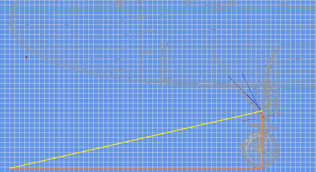
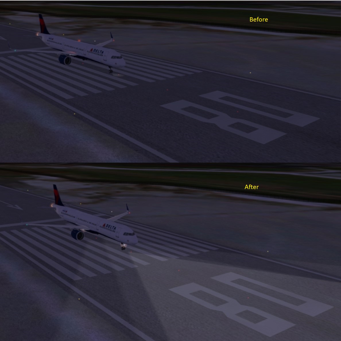
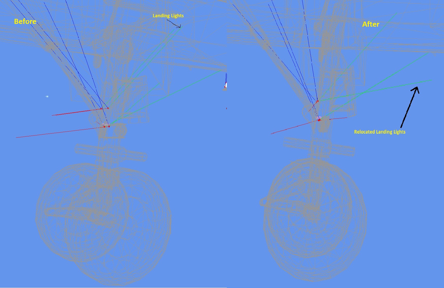
Now, I want to see where the light beam hits the ground.
For this matter I'll measure the height of the light beam above ground level and construct a right angled triangle
when I already know the base should be the same size as the height.
The next image shows the details:

Image

With the selected grid and grid cell sizes chosen its a mere 1.2 meters ahead of the front landing wheel which clearly explains
why the light was hardly seen on the runway.

After establishing the procedure's concept let's make a concrete example.
Suppose we want the light beam to hit the ground at a point that is straight beneath the cockpit's nose tip,
for this matter we construct a right angled triangle whose vertices are:
a. The light beam red (yellow) square.
b. The point where a vertical straight line from a. meets the ground
c. The point benath the cockpit nose tip at ground level

The next image clarifies the idea:

Image

Now we measure the base and height of this triangle.
If I'm not mistaken the base is 51 units in length and the height 11.5 units.
From this data we conclude the angle is: atan(11.5 / 51) = 12.707 degrees.

So 12.707 is the number we should plug into the Z rotation axis of the Attached Object Editor
dialog box to make the light beam hit the ground at the required point.

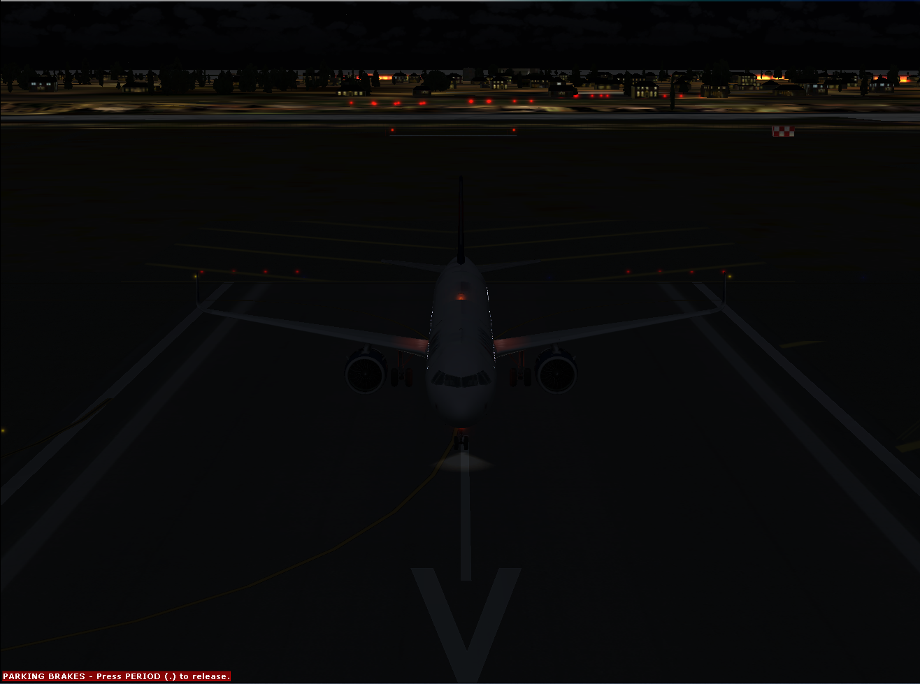
The next step is to export the model and test it in the sim.

Since the way your changes look in the simulator are the ultimate test, it is probable you'll
need to make small adjustment to make it right, so even though I presented a pretty methodical way
of calculating the proper angle some trial and error may still be needed...

Hope this helps
Regards
serbir
Ground hog
Ground hog
 
Posts: 15
Joined: Tue Apr 25, 2023 4:24 am


Return to Flight Simulator X (FSX) and Steam

Who is online

Users browsing this forum: No registered users and 1184 guests