This part was inspired by Sprockets' post - How I salvaged my Saitek yoke.
Unfortunately, I reacted badly in a post, and drove him off. Thanks, and good luck, Sprocket, wherever you went.Before you begin reading, look at the pictures. And then decide if you want to do this mod.Part two - All I wanted was ONE switch with a light that would turn on & off.I like buttons and switches.
No
shi* foolin'.

There are USB based controller boards that can be detected by just about any flight sim. They're called a HID
(Human Interface Device) device.
Push a button and most computers will detect it.
When you use a HID controller the computer will see something like this when you push a button:Device(0) Event: Button1 Down
Device(0) Event: Button1 Up
Device(0) Event: Button2 Down
Device(0) Event: Button2 Up
And so on. Different software may list the device & events in a slightly different way.
Sometimes instead of Device(x), it'll list the device by a name like this;Gamepad(0) Event: Button1 Down
Gamepad(0) Event: Button1 Up
If you're using two of these you'll see this;
Gamepad(0) Event: Button1 Down
Gamepad(0) Event: Button1 Up
Gamepad(1) Event: Button1 Down
Gamepad(1) Event: Button1 Up
These are the signals that your game needs to see and respond to.
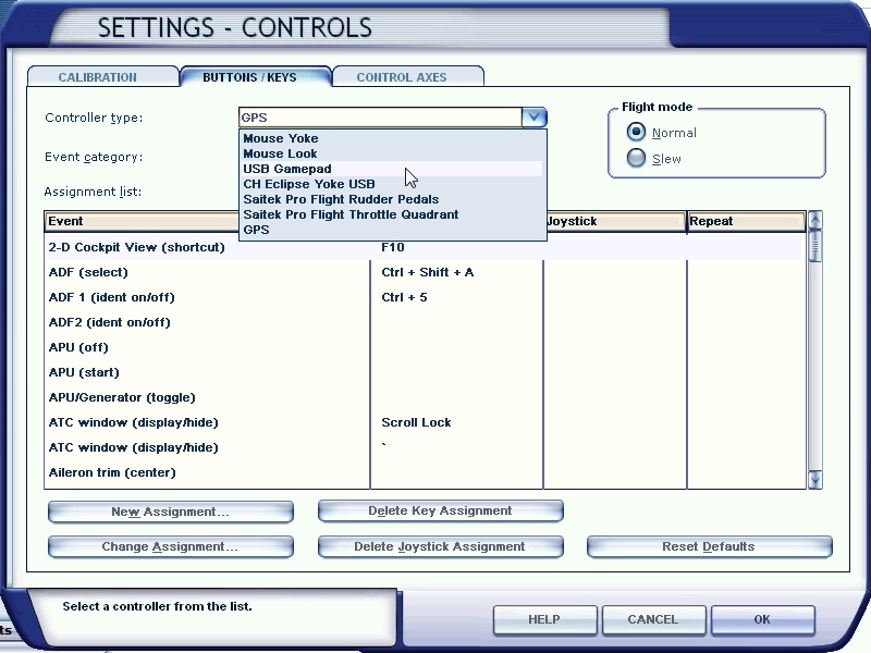
And just about anyone, who's using more than a mouse & keyboard, has probably programed their own equipment, so there should be no need to go into basics here.
There is a way to save a significant amount of money if you're willing to do a little bit of work.So how do you go about making a lighted switch turn on & off,
AND do something in FS9, FSX, Prepar3d, or in xxx?
This depends on your abilities and just what you have at hand.
POWER!I happen to have a 12VDC 1amp plugin transformer. And that saved me both money & effort.
Why?
That has to do with voltage, LEDs, and resistors.
LEDs need a certain amount & type
(DC as opposed to AC) of power.
I'm not going to get into the fine details about that stuff, but here are a couple of places to get you started
(in no particular order);
Choosing The Resistor To Use With LEDsForward Voltage and KVLLED Resistor CalculatorLED Series Resistor CalculatorI know. Nothing's simple, is it. But the more you learn, the better off you'll become.
But a lot of people may just want to go the way that I went.
You WILL probably have to buy the 12VDC transformer, but it doesn't need a 1 amp (1,000ma) output though.
And if you don't have spare transformers laying about your home, you'll need one anyway, so....
For just a few LEDs, 250 to 500 milliamps should be more than enough. But I'm just guessing on the 250ma.
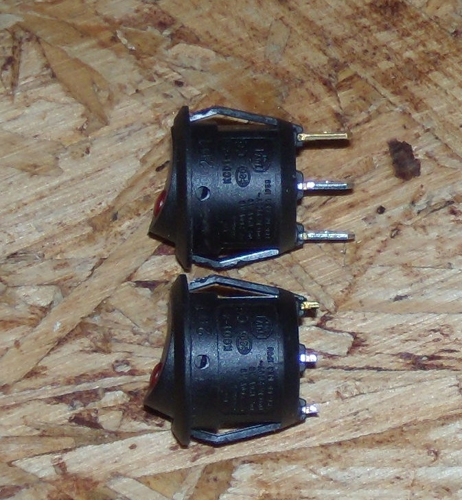
THE SWITCHES!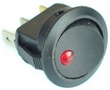 New 10PC Car Truck Rocker Toggle LED Switch Red Light On-Off ControlThese are;
Cheap - $10 for a bag of 10!
ONE DOLAR EACH!12VDC - They're already setup for 12VDC so they match my transformer. NO RESISTER NEEDED - They're made to work off a 12 volt auto system, so you don't have to do anything else.
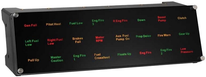
THE CONTROLLER BOARD!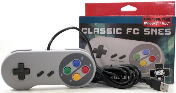
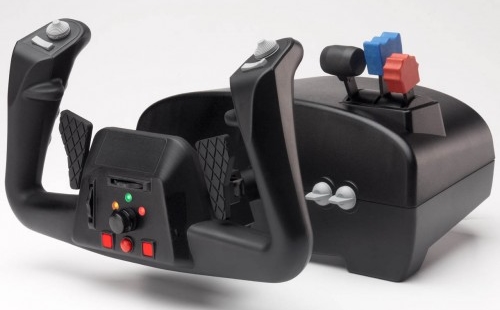
This is similar to what Sprocket used. I never had controllers like this, so I never thought of using them with FSX. But sometimes the simplest of ideas are pure genius.
I went to a couple of stores to get something like this, and discovered what most of you already know - They ain't all USB devices!
I also learned that they cost more than I wanted to spend at the moment, so off to Amazon.
Gtron USB SNES Classic Famicom Controller 9FT Cord for PC/MAC - PC Mac LinuxPrice - $8. THAT, I can afford.
But what I wanted was the board, to use as a controller. So....
This is the board with the wires soldered on to the printed circuit.
If you aren't used to soldering you might want to have someone else do that part.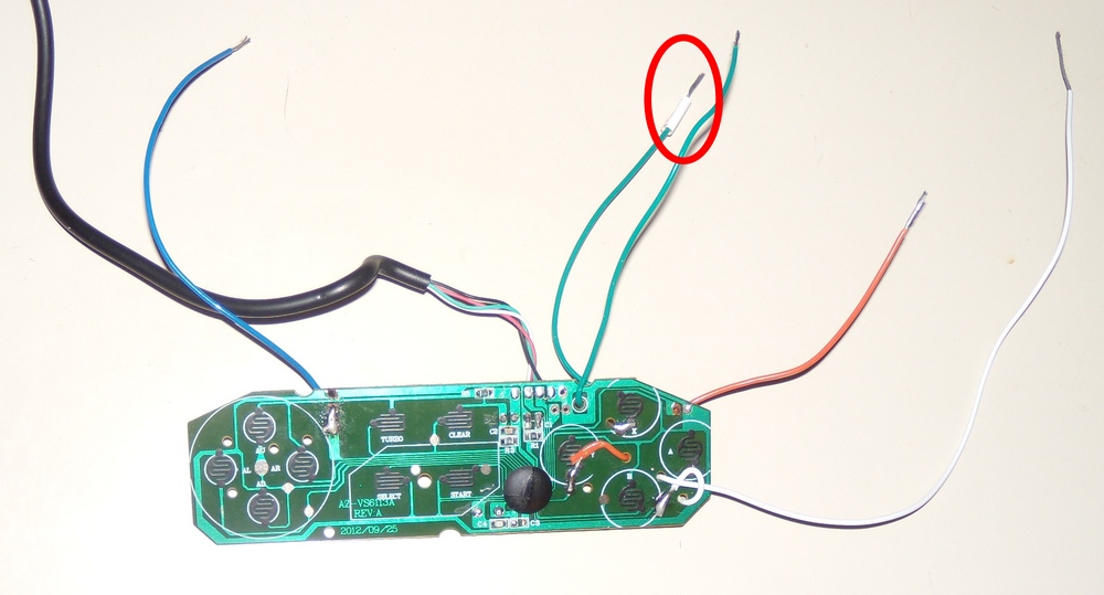
The wire with the white electrical tape on it is the "common" connection. If ANY of the other four wires make contact the board/computer will register a connection (button press down, button up).
After testing all four of the wire/connections, I wrapped the board up in electrical tape to prevent the wires from pulling the circuit board trace off the board.
If you buy a USB/HID controller this'll be less likely.
NOTE - I only
needed ONE button. But I could see a use for a total of 3 buttons. And if you could use 3, why not 4????
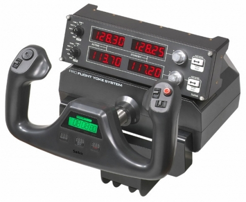
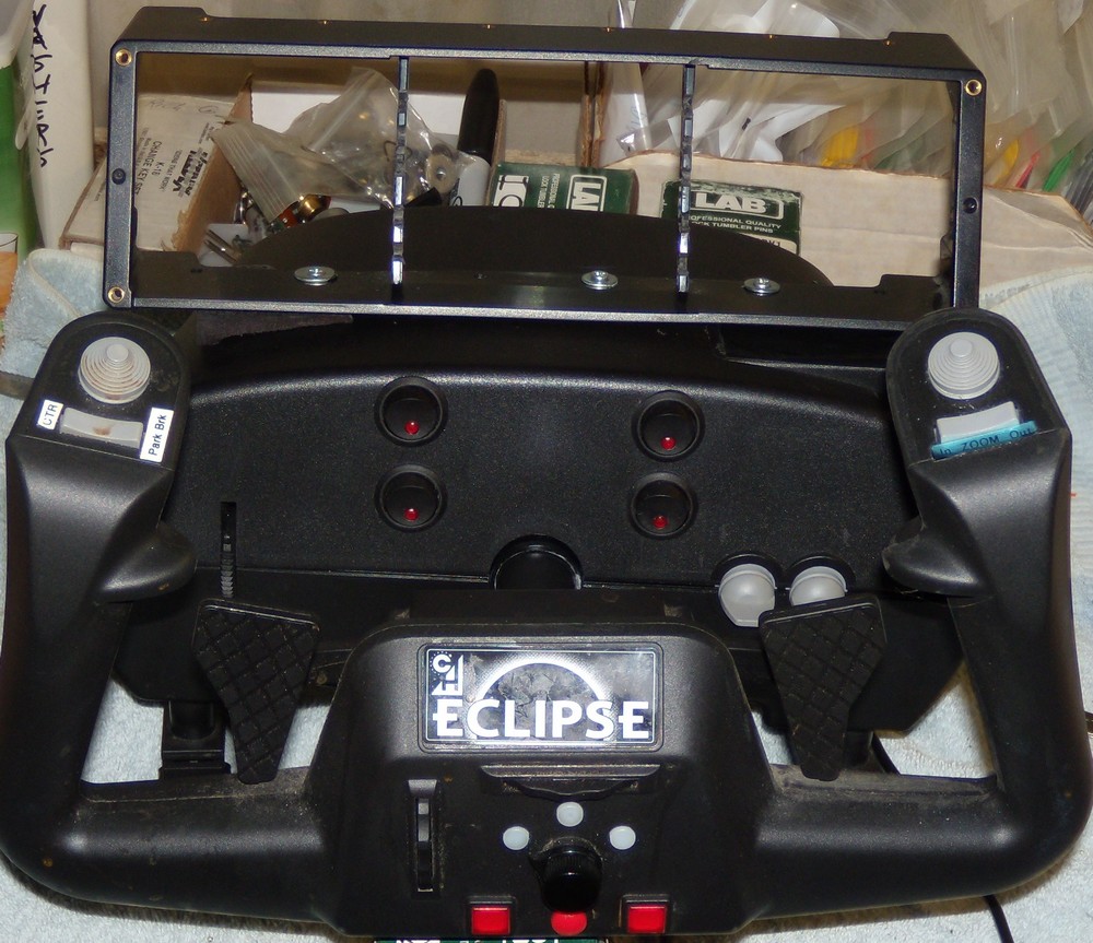
Four turned out to be the best option for the face of CH yoke. So four it was.
Using this board you could use up to eight buttons.
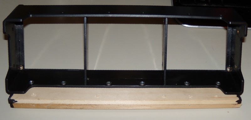
HOLES!The switches are intended to be press fit into holes. There is a "key" (rib) on one side so that they don't start to rotate once in place. The best way that I found to make the holes was to use what's called a "stepper" or Unibit.
Neiko 3-Piece Titanium Step Drill Bits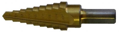
Mark everything off as best you can, drill a starter hole, and then progress the stepper bit, one step at a time, until the base of the button fits smoothly in. If you make the hole to big...... Good luck to you.
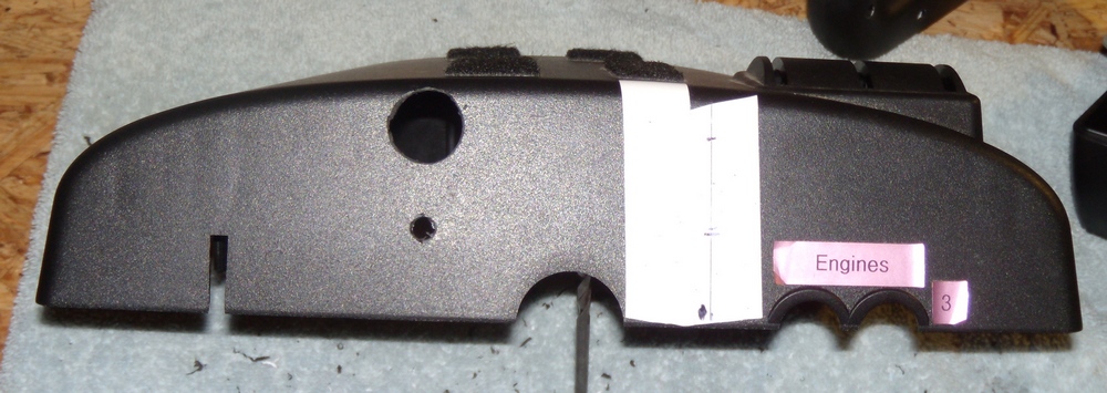 If you make the hole too small the switch will bind and be hard to work.Getting there.
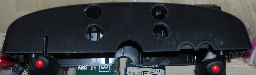
When the base of the button goes in you'll then have to file a cutout for the "key".
The switches will need to have the wires soldered on before inserting the switch.
TEST YOUR WIRING
BEFORE YOU PUT THEM IN.
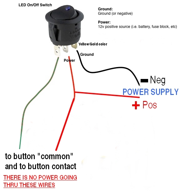
Hopefully this'll help for wiring the switch.
To get the 12 volts DC into the case for the LEDs, I installed a power connector/jack in the back of the case.
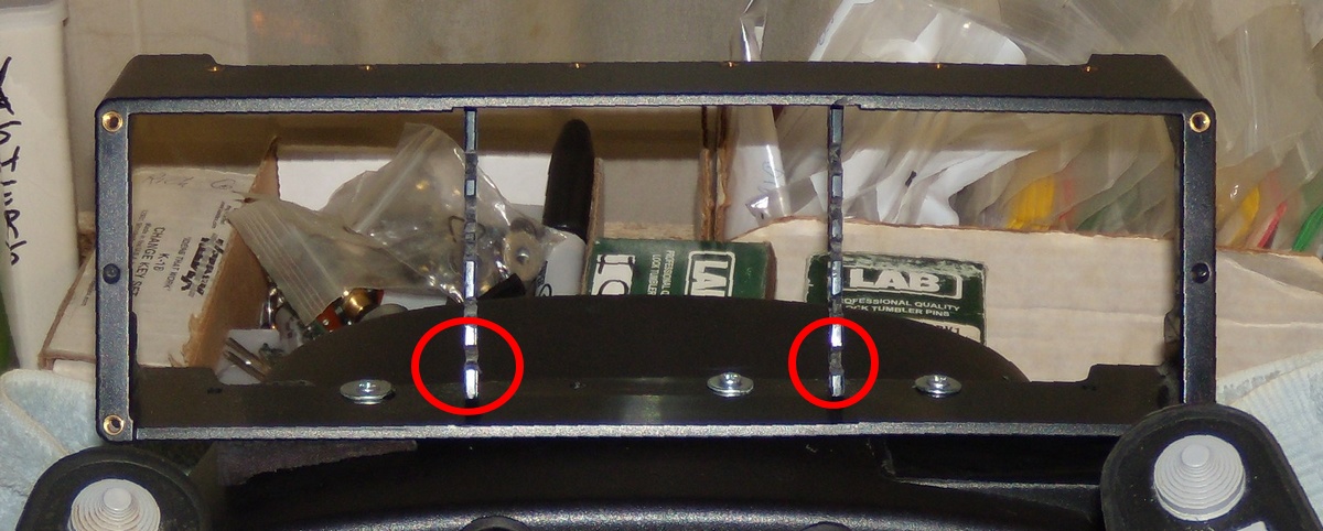
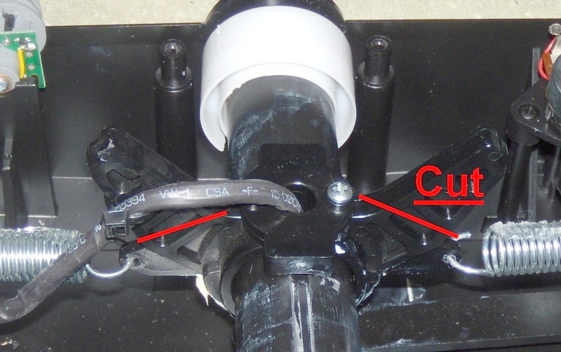
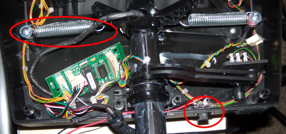 SIDE NOTE: The one thing that irritates me is the sound of the springs moving inside the case when you pull/push the yoke. A small stream of Silicone sealant across the springs (leave it over night) will keep them nice and quiet.While I'm at it, another SIDE NOTE 2: You don't have to do this while the top of the yoke is off, but put some white lithium grease on the shaft. It keeps it from binding.
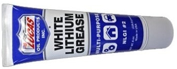
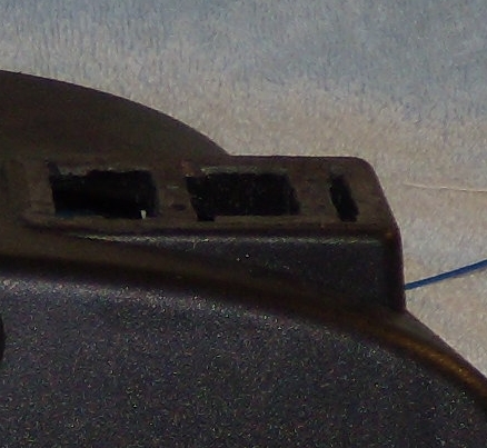
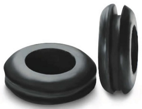
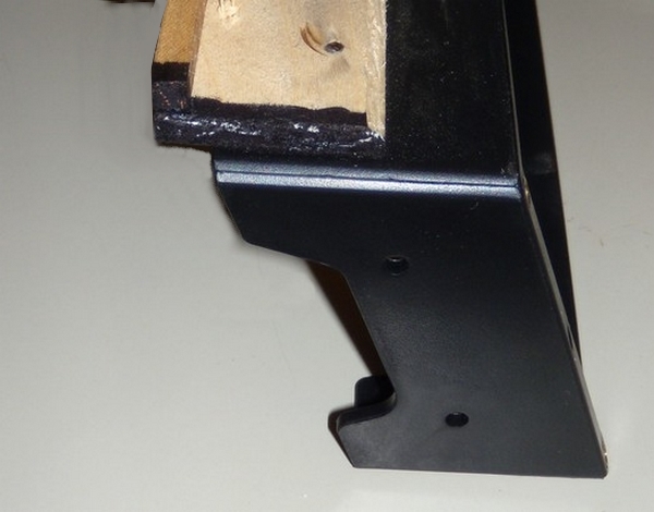
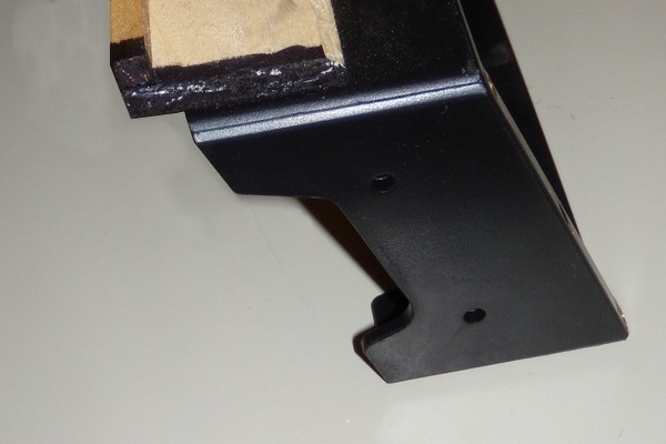
The USB Pass through was made by drilling a hole
JUST below the original USB cable pass through.
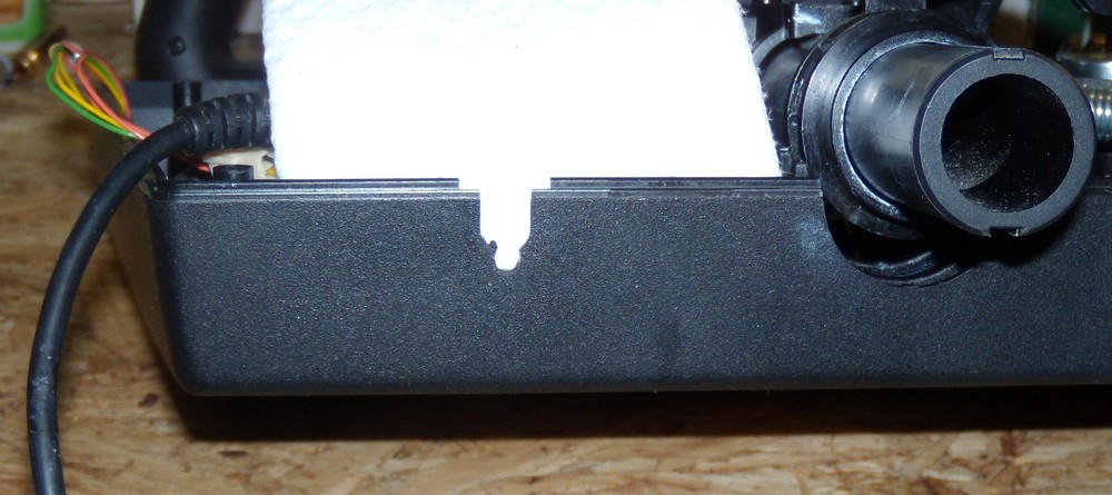
When the top part of the case is secured to the bottom, the grommet presses against the new cable hard enough to keep it from moving.
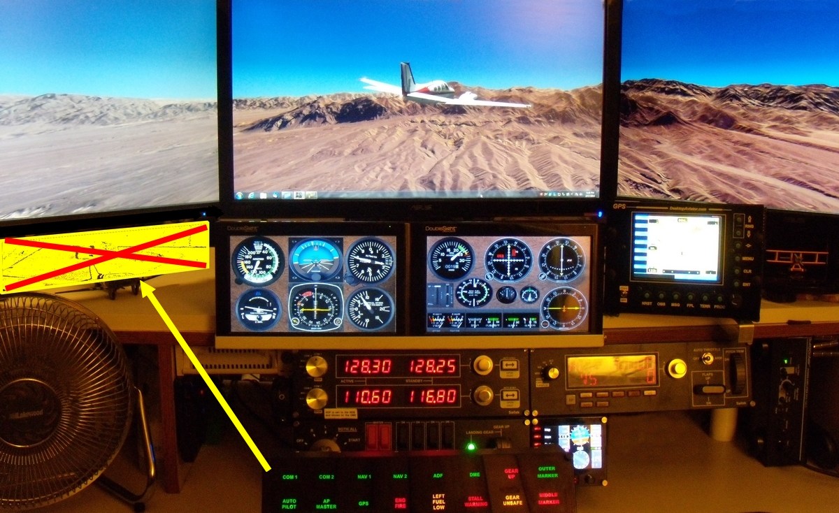
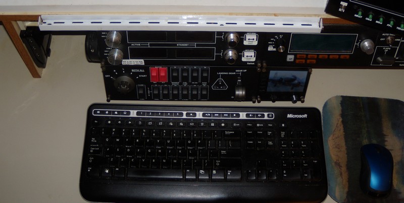
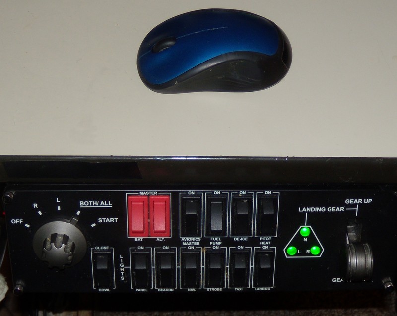
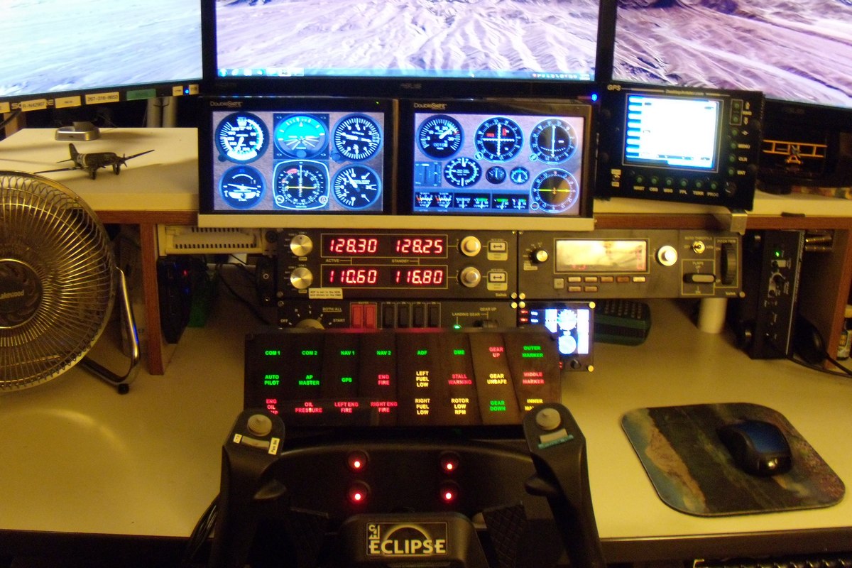
Everything is in place now.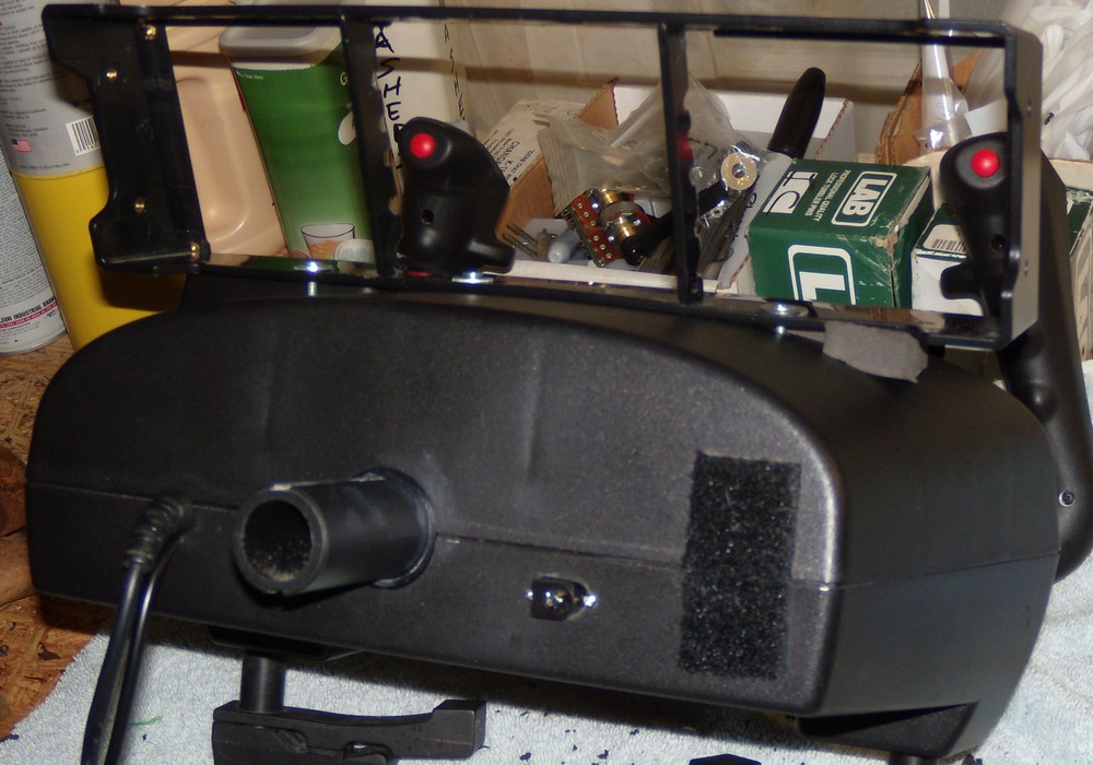
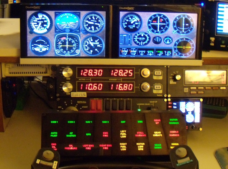
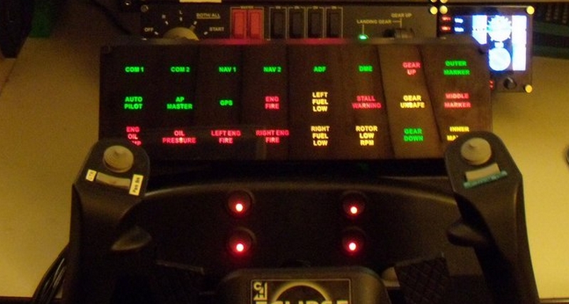
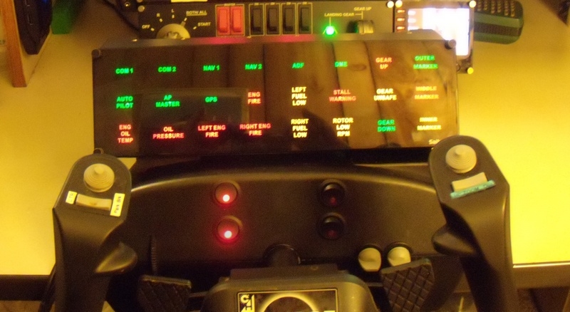
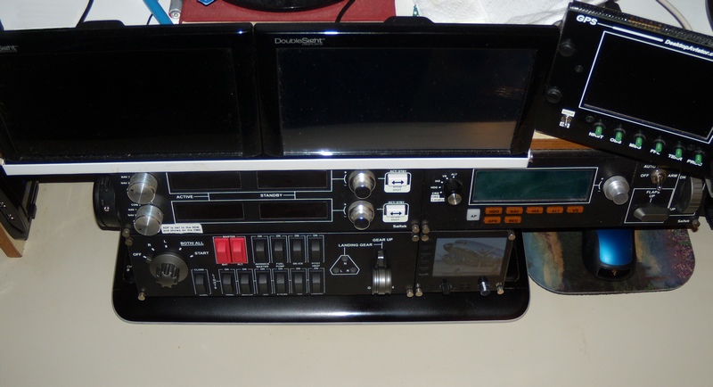
 Well. How did it look when done?
Not to bad, if I have to say so myself.
The pictures on the other hand...... Not so good.
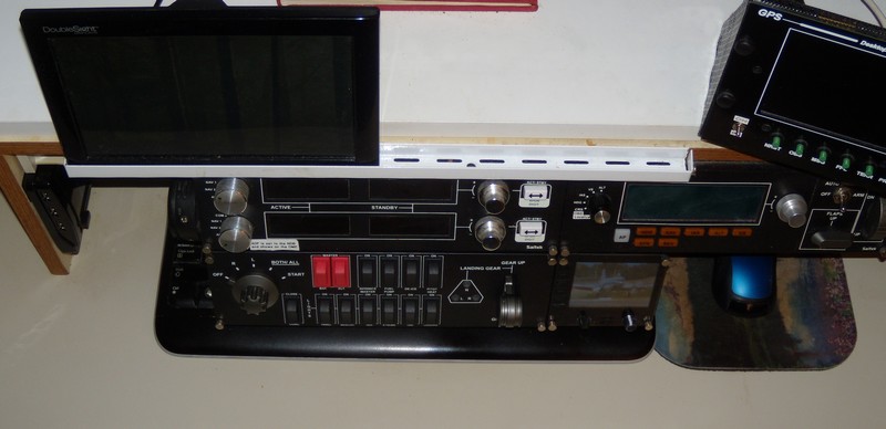
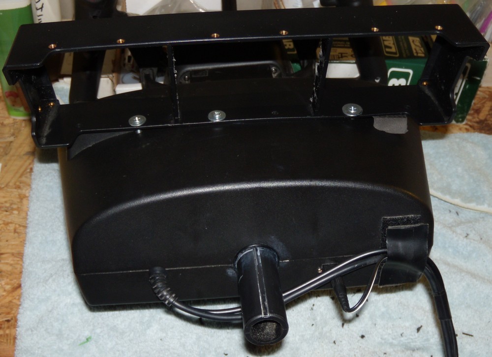
There's
more than enough room to reach in and flip any switch.
Actually, I just measured it - 9 inches (about 23 cm) between the switches and the back of the yoke.
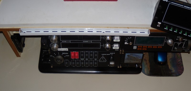
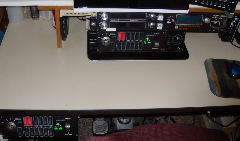
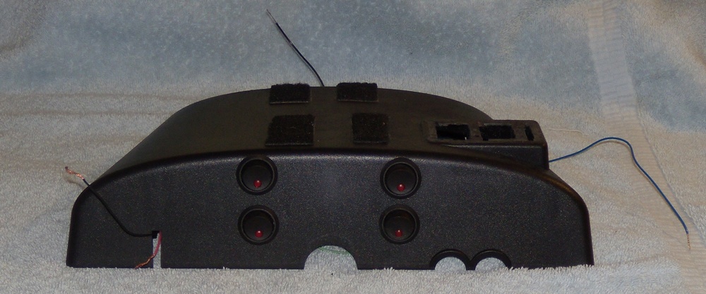
This shot is AT EYE LEVEL looking down. A word of warning before you decide to do this - WAIT FOR THE LAST INSTALLMENT!