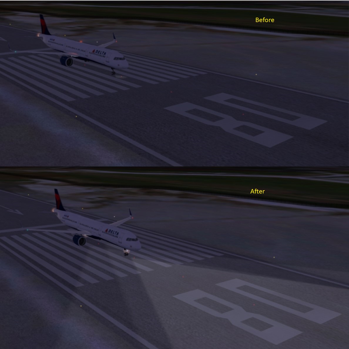
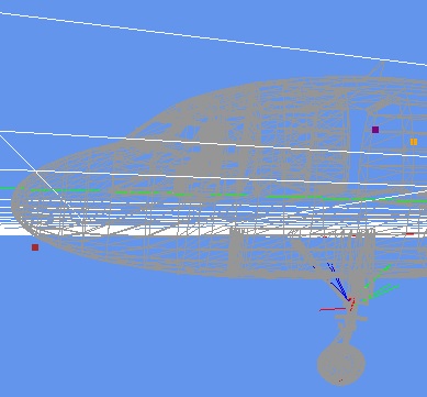
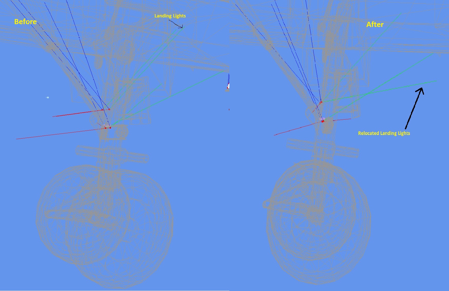
I admit that in this particular case I've used the trial and error approach.
Nevertheless I'll explain how it can be done using a more methodical procedure.
It is important to understand that MCX is not a fully fledged graphical 3D modelling tool and as such
it has limitations and doesn't provide tools to acomplish simple tasks such as measuring distances for example.
(as far as I am aware of)
I will also assume that you know how to navigate your way inside MCX, I definetly do not want this answer
to became a full MCX tutorial, so if a refer to a certain menu or icon you should select or press, please
search the internet for tutorials on MCX, there are plenty of them out there.
The explanation will be done on the same model as in the previous posts.
So, let's get started:
a. Open MCX
b. Load the exterior *.mdl file of the model in question
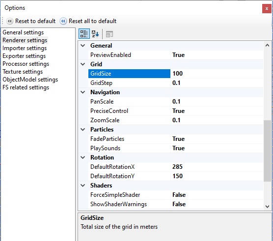
c. Open the Options Menu and set the Grid and Navigation values to suite your needs
The following is a good starting point:
d. Select the wire frame mode of viewing the model
e. Press the 'Camera view mode' selection arrow and choose 'Left'
f. Move the animation arrow bar completely to the right so the landing gear is open
and in the compressed position which corresponds to an airplane sitting on the ground
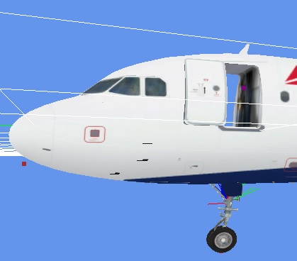
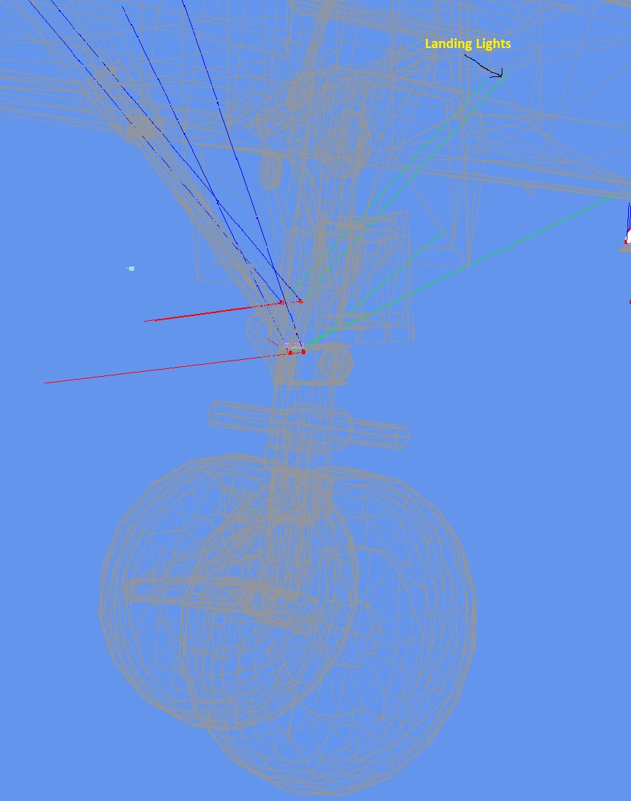
The following is a detail of the area of interest:
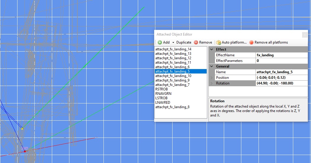
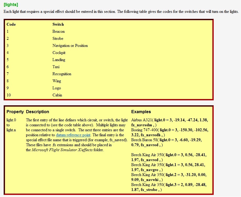
I've also opened the 'Attached Object Editor' window and selected the 'attachpt_fx_landing_5'
item which I know for sure is a landing light.
Note that when an item is selected its red dot became yellow so its easier to identify it amongst
the other attached effects.
In this particular model there are 10 attached light effects where four of them are landing lights
and the others are taxi lights.
As can be seen in the 'Attached Object Editor' there are some parameters on the right hand side that we can play with,
the most interesting being the Position and Rotation.
Unless you find the attach point is way off place there is no need to tamper with the Position parameters.
On the other hand the rotation in the vertical axis (Z) seems too steep, a clear candidate for improvement.
By the way the Z,Y and X rotations correspond to the vertical, lateral and longitudinal axes.
I want to know the angle of incidence of the landing light beam represented by the upper green trace.
For this matter I'll contruct a right angled triangle where the green line is its hypotenuse, as seen in the
following image:
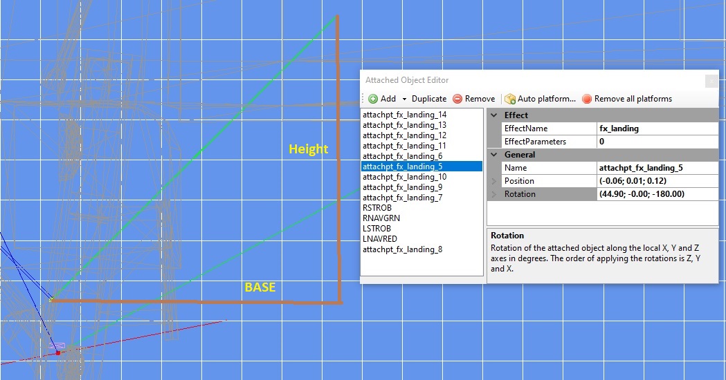
I can compute the angle of incidence of the light beam (the angle between the hypotenuse and base sides of
the triangle) if I know its tangent, which by the way is the cotient of the triangle's height by its base. as we remember
from our trigo classes.
Now comes the clumsy part: since MCX does not have a distance measuring tool, we need to count
grid cells.
As can be seen they are both approximatly the same 7 units in length (the base is a bit longer but I'll disregard this detail)
so the angle's tangent is equal to 7/7 = 1.
Now using our favorite scientific calculator we find that the inverse tangent (inv tan or atan if you prefer) is 45 degrees
which pretty much matches the 44.90 degrees rotation in the Z axis as depicted in the Attached Object Editor above.
You may increase the precision of the measurement by decreasing the grid's step size but at some point it
will become increasingly dificult to count those little squares. Your choice.
Now, I want to see where the light beam hits the ground.
For this matter I'll measure the height of the light beam above ground level and construct a right angled triangle
when I already know the base should be the same size as the height.
The next image shows the details:
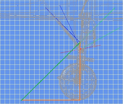
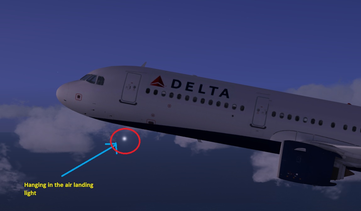
With the selected grid and grid cell sizes chosen its a mere 1.2 meters ahead of the front landing wheel which clearly explains
why the light was hardly seen on the runway.
After establishing the procedure's concept let's make a concrete example.
Suppose we want the light beam to hit the ground at a point that is straight beneath the cockpit's nose tip,
for this matter we construct a right angled triangle whose vertices are:
a. The light beam red (yellow) square.
b. The point where a vertical straight line from a. meets the ground
c. The point benath the cockpit nose tip at ground level
The next image clarifies the idea:
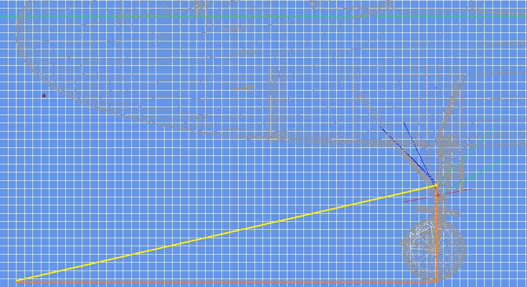
Now we measure the base and height of this triangle.
If I'm not mistaken the base is 51 units in length and the height 11.5 units.
From this data we conclude the angle is: atan(11.5 / 51) = 12.707 degrees.
So 12.707 is the number we should plug into the Z rotation axis of the Attached Object Editor
dialog box to make the light beam hit the ground at the required point.
The next step is to export the model and test it in the sim.
Since the way your changes look in the simulator are the ultimate test, it is probable you'll
need to make small adjustment to make it right, so even though I presented a pretty methodical way
of calculating the proper angle some trial and error may still be needed...
Hope this helps
Regards


