Construction Started On Cockpit Center ConsoleI managed to steal about 3 hours last night from 10 PM to 1 AM to get started on constructing the center console portion of my simulated cockpit. The basic construction techniques here are the same as what was done for the part that I documented in a post prior to this one in this thread.
All of the design work was done in my CAD program and I again just transfered the dimensions onto the wood. The center console is constructed mainly out of 1/2" medium density fiberboard, with 1/8" fiberboard "whiteboard" material for the panel facings. All of the main wood for the console came out of 1/2 of a 4' x 8' sheet. It is screwed and glued using scrap pine furring strips. Total cost for this part was again about $12 USD.
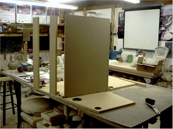
Photo #1
As You can see in Photo #1 above...... I spent some time playing with the monitor that I want to add in here as a FMC / TCAS radar display. Here I am checking to make sure that the dimensions are going to match the CAD design....... because I did not leave a lot of room here for this! The paper CAD plans are in the foreground. The already partially built throttle quadrant was also used to help visualize if this is going to all work out OK ;).
I really want to have that extra monitor in this console. There are just too many things that you need to display in a large jet cockpit ;). This will bring the number of monitors for the "glass cockpit" part of this cockpit project to four. It will be driven by my old Tcera laptop...... which is small and can be tucked into a nook somewhere.
The monitor I am utilizing here is one I picked up at the dump a week and a half ago. People just throw this kind of thing out. It is a 7 3/4" x 10 1/4" display, monochrome white, 604 x 480 vga display in perfect working condition. The monochrome is perfect for a TCAS type display...... although I would have prefered green, not white. "One man's junk is another man's........ "
To save space in the console I decided to strip the housing off most of the monitor. I just left the facing portion on the monitor to serve as a "flange" to mount it in the wood construction. If you are following this project and decide to do this also.......
be vary careful with opening monitors! They can have pretty lethal charges still in them even when unplugged. Watch how you handle them. And the picture tube can implode badly if you bang it on anything.
Photo #2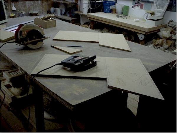
Photo #2 shows the two main side panels cut out. Note the sloping upper console section. This area takes the most planning. The edges of the boards you use must have the same slope so that the facing fits against it correctly. Using a skillsaw at an angle is sufficient for these cuts..... you don't NEED a tablesaw.
The two side pieces were cut out and then set "back to back" to compare the cuts. Slight adjustment was done with a saber saw so that the two matched as well as possible.
With careful planning the "scrap" from the two side panels will make all the other pieces.
Photo #3
In photo #3 you can see the trickiest cut in the project. This large flat sheet with the bevel cut edge is the top rear console wall. This angled cut has to match the slope of the upper portion ofthe console. I used the skillsaw set at an angle. The corner braces also have to be cut at an angle to match. You can see the "screw and glue" construction here too.
Photo #4
In photo #4 you see the rear console wall where it butts up against the main panel support structures. This section is cut out to allow good air circulation for the FMC/TCAS monitor that will be located there. I will also likely install some boxer fans near each monitor in the setup (with "real" cooling controls located on the overhead panel) to help keep them all cool. The holes in the bottom serve for more wiring passthroughs. The corner construction of the "box" is also evident here.
Photo #5
Photo #5 shows the internal structure of the console a bit. The wall that separates the lower console from the upper part does not go all the way to the bottom. This will allow the lower area to be utilized to store all manner of electronic stuff. It also facilitates wiring passthrough. The "dividing wall" will get a strip of furring along it at the level of the lower panel facing to help support that material.
This lower section will eventually get some internal dividing and supporting walls. These will be spaced to match the electronics that will get installed there. I already know that on the lower left... next to the pilot seat...... there will be a section set up to take a couple of Goflight radio units. So there will be a wall set up to support them on their panel mounting width of 7 1/4".
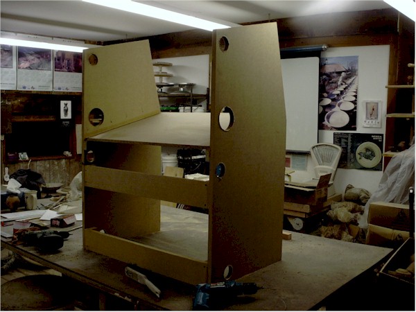
Photo #6
In photo #6 you can see the "stripped" monitor set in place in the upper center console. The mount is simply two furring strips screwed into the console walls at the appropriate height so that the monitor face is flush with the console face. The console panel facing will go over this...and have a cutout for the display screen. The monitor is "friction fit" here.... no mounting screws or anything..... it just sits on the flange created by the wood. It's quite stable 'cause the fit is so tight all around ;). But it is easily lifted in and out for doing any work. The two screws on the left side of the "mount" are evident on the dividing wall. They will be covered by the throttle quadrant.
Photo #7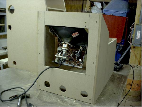
In photo #7 you see the center console from the rear, showing the monitor in place. The ease of access to the monitor workings is self evident. Also the wiring passthrough holes. The monitor does NOT project beyond the outside of the rear wall..... so that the console will butt up flush with the other support structures for the main panel.
Photo #8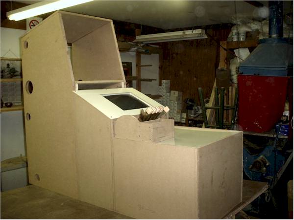
Photo # 8 shows the state of the project at this time. The center console has had the sheets of 1/8" fiberboard "whiteboard" cut and put in place. The hole for the monitor display in the upper panels section was cut out by drilling holes at the corners and then cutting with a sabre saw. The throttle quadrant is just sitting on top of the lower console section at the moment. The center console in this picture is butted up into its desired position next to the shelf unit that will hold the engine management display monitor and glaresheild (see prior posting in this thread).
So..... there you have the details about the status of my crazy "homebrew simulated cockpit" efforts so far. There are 5 hours of labor so far into the cockpit "framing" part of this project. Hope this documentation is inspiring someone else to "take the plunge" with this kind of thing

. Undertaking this project is an incredible amount of
fun! And I haven't even FLOWN in it yet!
More as it all develops.
best,
.....................john
 Intel i7 960 quad 3.2G LGA 1366, Asus P6X58D Premium, 750W Corsair, 6 gig 1600 DDR3, Spinpoint 1TB 720
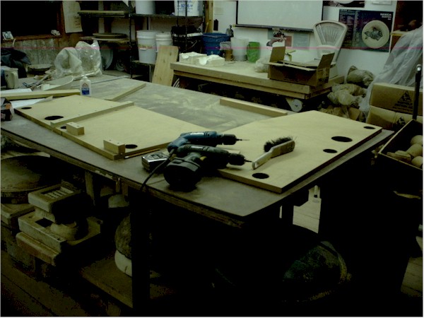


 . Because it is modular...... I could always add the right seat in the future....by just duplicating the stuff on the left of the center console over on the right. That just about doubles the cost. Plus then to be realistic.....you have to mechanically (or electronically) link the yokes. Expensive!