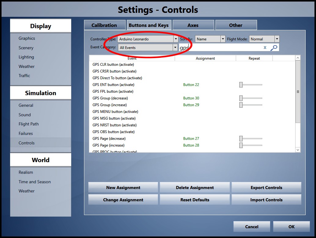
The guy who developed SPAD.neXt has built, and is testing, an interface connecting FS9, FSX, P3d, and X-Plane to an Arduino board.
SPAD.neXt works with all of those already, but his Arduino-flight sim interface would allow the use of 7 segment displays & servo motors in addition to button/encoder/joystick with your flight sim.
In short - You could make your own digital & analog instruments.
He CAN do it now, but he has to make it fool proof. If he can do that, then the sky is literally the limit.
This is his short transponder code video. (this was a test WITHOUT the 74HC595 shift registers)
[youtube]http://www.youtube.com/watch?v=AU4-EY0xUzE[/youtube]
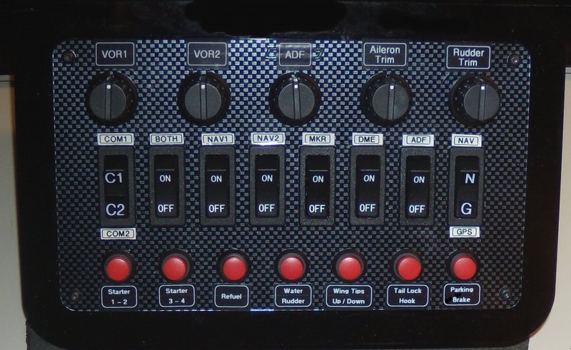
You can use an Arduino to make simple button boxes as I've already done, and you don't need SPAD.neXt to use a button box. SPAD.neXt just lets you do a lot more with it than the joystick buttons built into your flight sim.
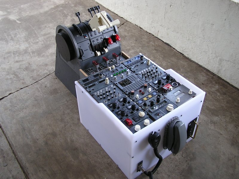
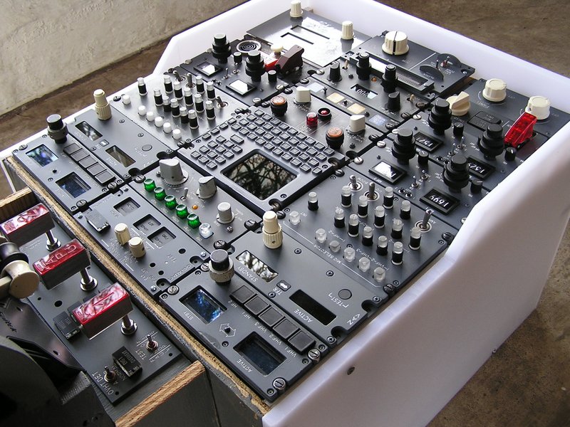
However, you would also be able to make anything from Saitek type panels up to full cockpits.
The best thing is that this is not rocket science. And it also is not very expensive.
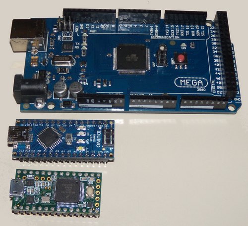
One of the two boards that he's using right now is the Teensy 3.5, so I ordered one and have been testing it with a digital display.
This picture shows several Arduino boards. The 7 segment display is hooked up to the Teensy 3.5.
Sorry for the poor picture quality.
 In real life all the numbers are evenly lit, and quite bright.
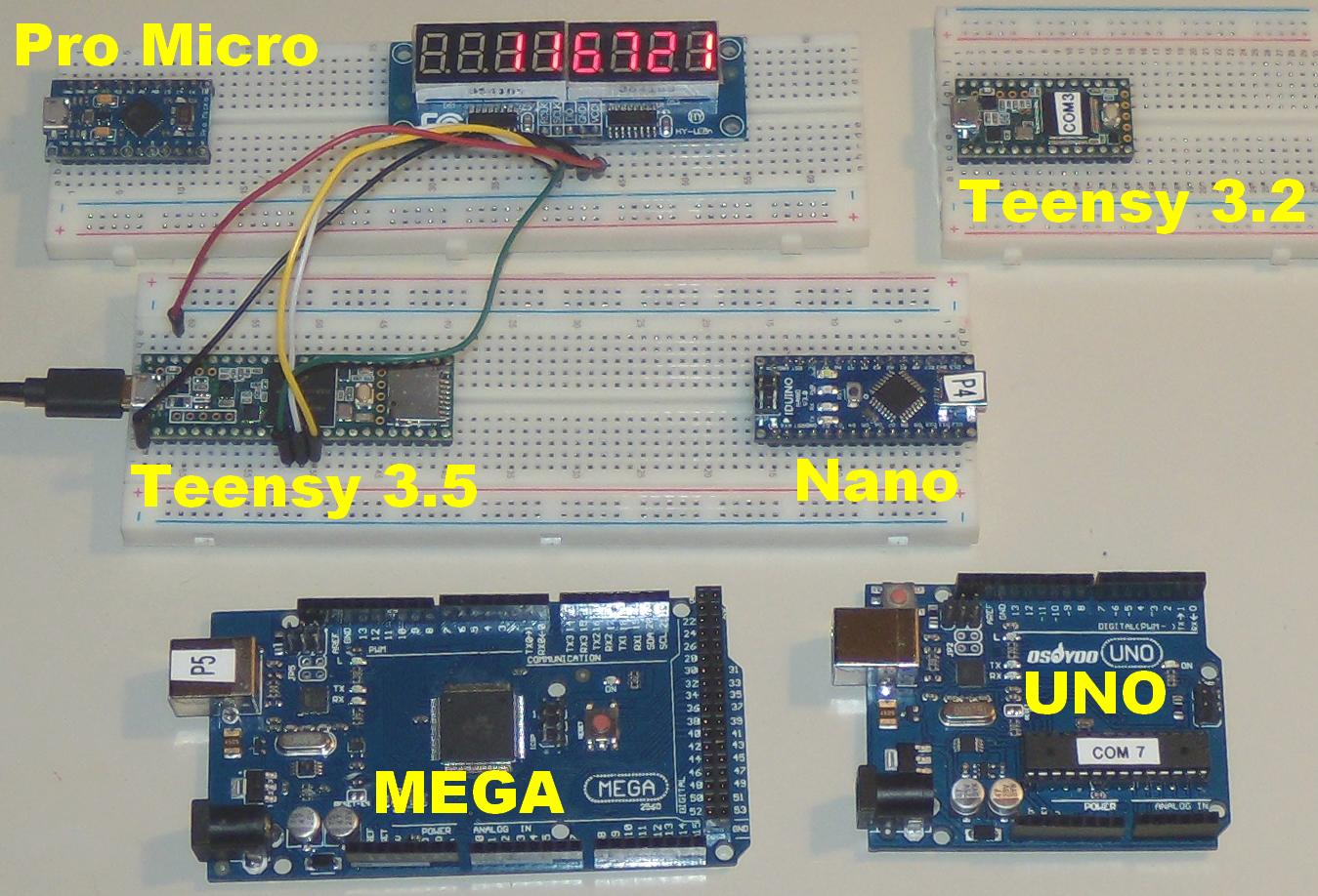
ALL of the Arduino boards above can use the same code to work the display.
If you want to play around with a similar display, you can use the code below.
NOTE - The display board that I'm using has two 74HC595 shift registers. These are very common, BUT they are not the only ones in use.
The display board that I'm using is this one - XINY 8-Digit Digital Display Control Module 8-Digit 7 Segment Digital LED Display Tube $7.60. Similar boards with two 74HC595 shift registers SHOULD work just as well.
Just copy and paste this code (from playground2014) into the Arduino IDE. No modifications needed.
/*
Modify from Liquid Crystal example
For 8 x 7 segment module
*/
#define LATCH 12 //pin 12 of BBFuino connect to RCK of 8x7segment module
#define CLOCK 11 //pin 11 of BBFuino connect to SCK of 8x7segment module
#define DATA 10 //pin 10 of BBFuino connect to DIO of 8x7segment module
#define LED 13 //LED is connected to pin 13 of Arduino
#define MultiplexDelay 1 //delay for multiplexing between digit on 8x7segment module
#define LEFT 0 // define the value for left justify
#define RIGHT 1 // define the value for right justify
#define BLANK 11 //array element to make 7segment blank
// array to activate particular digit on the 8x7segment module
// it is the common anode of 7 segment
byte anode[8] = { 0b10000000, //digit 1 from right
0b01000000, //digit 2 from right
0b00100000, //digit 3 from right
0b00010000, //digit 4 from right
0b00001000, //digit 5 from right
0b00000100, //digit 6 from right
0b00000010, //digit 7 from right
0b00000001 //digit 8 from right
};
//array for decimal number, it is the cathode, please refer to the datasheet.
//therefore a logic low will activete the particular segment
//PGFEDCBA, segment on 7 segment, P is the dot
byte cathode[12] = {0b11000000, // 0
0b11111001, // 1
0b10100100, // 2
0b10110000, // 3
0b10011001, // 4
0b10010010, // 5
0b10000010, // 6
0b11111000, // 7
0b10000000, // 8
0b10010000, // 9
0b01111111, //dot
0b11111111 //blank
};
//fucntion to send the serial data out to two 74HC595 serial to parallel shift register and activate the 7 segment.
void display8x7segment(byte datapin, byte clockpin, byte latchpin, byte digit, byte number)
{
digitalWrite(latchpin, LOW);
shiftOut(datapin, clockpin, MSBFIRST, digit); // clears the right display
shiftOut(datapin, clockpin, MSBFIRST, number); // clears the left display
digitalWrite(latchpin, HIGH);
}
//function to display value on 8x7 segment display according to the justify state
void displayNumber8x7segment(byte justify, unsigned long value)
{
byte decimal[8] = {0};
value = value % 100000000; //ensure the value is within 8 digits only
decimal[7] = value / 10000000; //extract digit 7 from value
value = value % 10000000; //extract the rest of 7 digit value
decimal[6] = value / 1000000;
value = value % 1000000;
decimal[5] = value / 100000;
value = value % 100000;
decimal[4] = value / 10000;
value = value % 10000;
decimal[3] = value / 1000;
value = value % 1000;
decimal[2] = value / 100;
value = value % 100;
decimal[1] = value / 10;
decimal[0] = value % 10;
byte zero = 0;
if (justify == RIGHT)
{
for(byte e = 8; e > 0 ; e --)
{
if(zero == 0)
{
if(decimal[e-1] != 0)
{
display8x7segment(DATA, CLOCK, LATCH, anode[e-1], cathode[decimal[e-1]]);
zero = 1;
}
}
else display8x7segment(DATA, CLOCK, LATCH, anode[e-1], cathode[decimal[e-1]]);
delay(MultiplexDelay);
}
}
else //if justify == left
{
byte d = 0;
for(byte e = 8; e > 0; e --)
{
if(zero == 0)
{
if(decimal[e-1] != 0)
{
display8x7segment(DATA, CLOCK, LATCH, anode[7], cathode[decimal[e-1]]);
zero = 1;
d ++;
delay(MultiplexDelay);
}
}
else
{
display8x7segment(DATA, CLOCK, LATCH, anode[7-d], cathode[decimal[e-1]]);
d ++;
delay(MultiplexDelay);
}
}
}
}
void setup() {
pinMode(LATCH, OUTPUT);
pinMode(CLOCK, OUTPUT);
pinMode(DATA, OUTPUT);
pinMode(LED, OUTPUT);
digitalWrite(LATCH, HIGH);
digitalWrite(LED, LOW); //off LED
// set up the LCD's number of columns and rows:
delay(1000); //delay for 1 second
}
void loop(){
//1st demo, 8x7segment will display decimal value from 0 to 9 and dot from 1st digit (most right) until the last digit (most right)
for(byte i = 0; i < 8; i++)
{
for(byte k = 0; k < 11; k++)
{
display8x7segment(DATA, CLOCK, LATCH, anode[i], cathode[k]);
delay(300);
}
}
delay(1000); //delay 1 second
//2nd demo, 8x7segment will display same decimal from 0 to 9 and dot across all 8 digit
for(byte k = 0; k < 11; k++)
{
display8x7segment(DATA, CLOCK, LATCH, 0xff, cathode[k]); //activate all digit
delay(300);
}
delay(1000); //delay 1 second
//3rd demo, 8x7segment will display a decimal value increasing like normal counter.
for (unsigned long value = 0; value < 100000000; value ++)
{
for(byte i = 0; i < 10 ; i ++)
{
displayNumber8x7segment(RIGHT, value); //display the value in right justify format
}
}
delay(1000);
}