How I salvaged my Saitek yoke
My Saitek Yoke went dead quite a while past, but instead of bining it, I thought I would see if I could salvage it if possible.
Well, I finally got down to it, and thought I would share the "salvage operation" on here for the benefit of others.
(Notice that it is not a repair.)
With the unit totally dead, the logical thing to do is to replace the circuit board with that of another suitable joy stick. This is what I done, as follows:
I found a suitable replacement circuit board to be from a USB games controller.
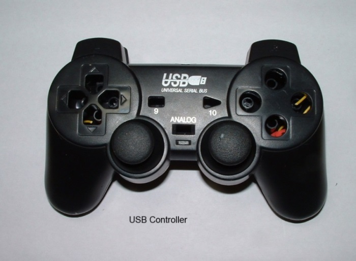
This unit comes with:
1. two thumb joysticks, each one with an analogue x/y axis, (Aileron and elevator on the one, throttle and mixture on the other one.)
2. A set of dedicated POV buttons, needed also for the Saitek POV. (Point of View)
3. 10 Switches for the hand controls.
(The first test I done was to see whether I could replace the x/y pots directly with the Saitek pots, and found them 100% compatible. (ie, it calibrates correctly).
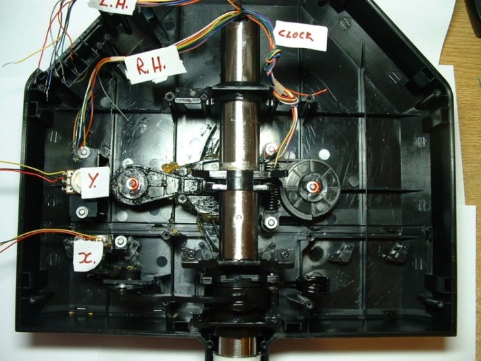
First thing is to identify the Saitek wire connections. I found that the wires are bundled together in three groups, or looms.
One loom for the Left hand buttons, one loom for the Right hand buttons and one loom for the center clock. (Which we don't need)
Following is the button designated colours. (Colors for our USA friends )
)
The left hand button loom has 8 wires, as follows:
(Common to all the LH switches = Orange)
1. POV Up = Slate (Light grey)
2. POV Down = Blue
3. POV Left = Green
4. POV Right = Dark blue
5. A1 = Red
6. A2 = Brown
7. E = Yellow
8. Common = Orange
The right hand button loom has 9 wires, as follows:
(Common to all the RH switches = Red)
1. B1 = Black
2. B2 = Orange
3. C1 = Yellow
4. C2 = Brown
5. D = White
6. Mode 1 = Slate
7. Mode 2 = Green
8. Mode 3 =Blue
9. Common = Red
Next consideration are the two Saitek pots, X Axis for Alerons, Y Axis for Elevator. See photo:
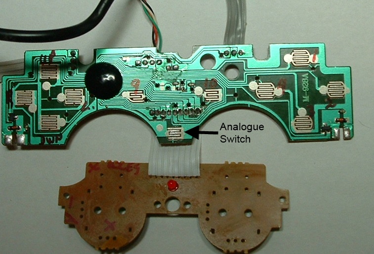
Next is to prepare the USB controller board: This is the board as removed from the USB unit.
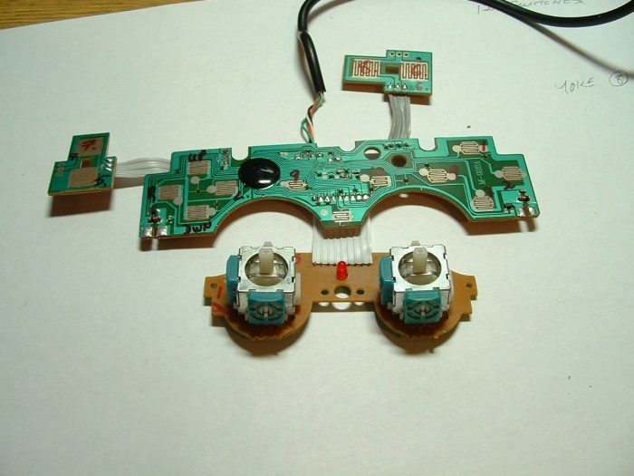
Next I removed the two joy sticks, AND soldered in 5 jumper wires - because connection was previously by the joystick metal bodies.
And now you can see where it is leading, can't you.
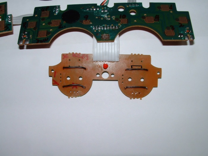
The following photo identifies the USB switch positions.
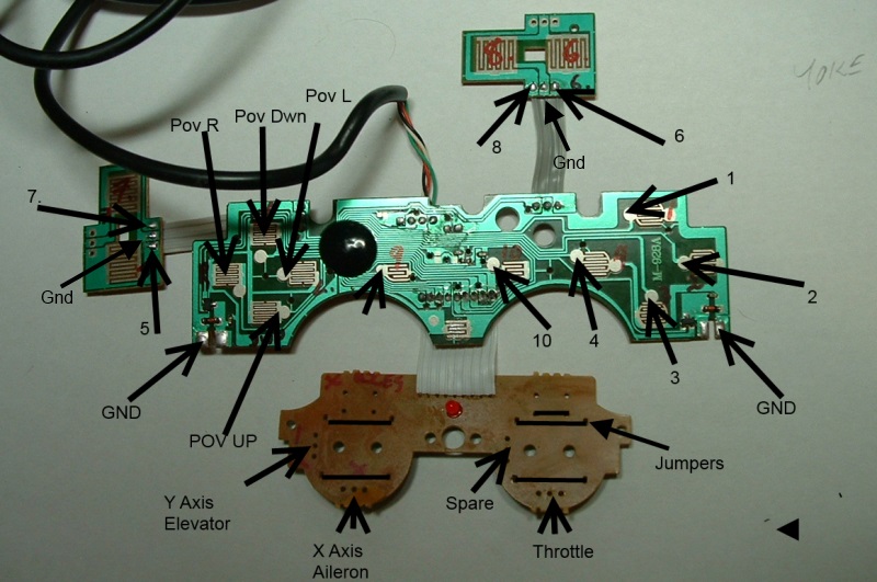
With the exception of the POV wiring and the pots, any of the yoke buttons can really be wired to any of the switches - mapping can be sorted in the FS itself.
But there remains one very important nuisance.
These USB controllers can operate in either "switch" or "Analogue" mode and we need to ALWAYS be in analogue mode.
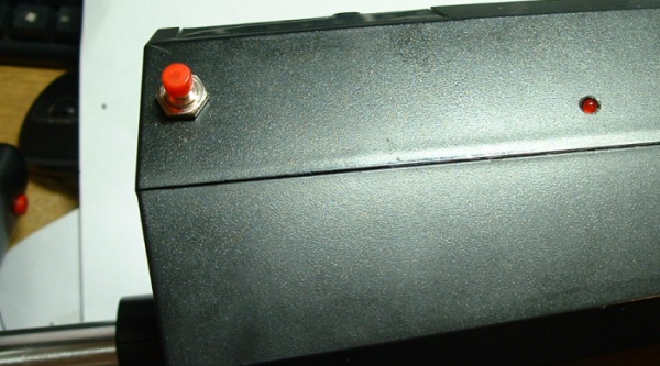
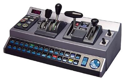
On starting up, they default to switch mode. To switch to analogue mode, there is a small push button
on the front of the controller, and an LED to indicate. (See the very first photo). Problem is this button needs to be a momentarily switch, meaning it cannot be hard wired.
To overcome this, I installed a small N/O pushbutton switch on the side of the Saitek housing, as well as a 3mm hole for the indicator LED.
The switch is then wired to the board as follows:
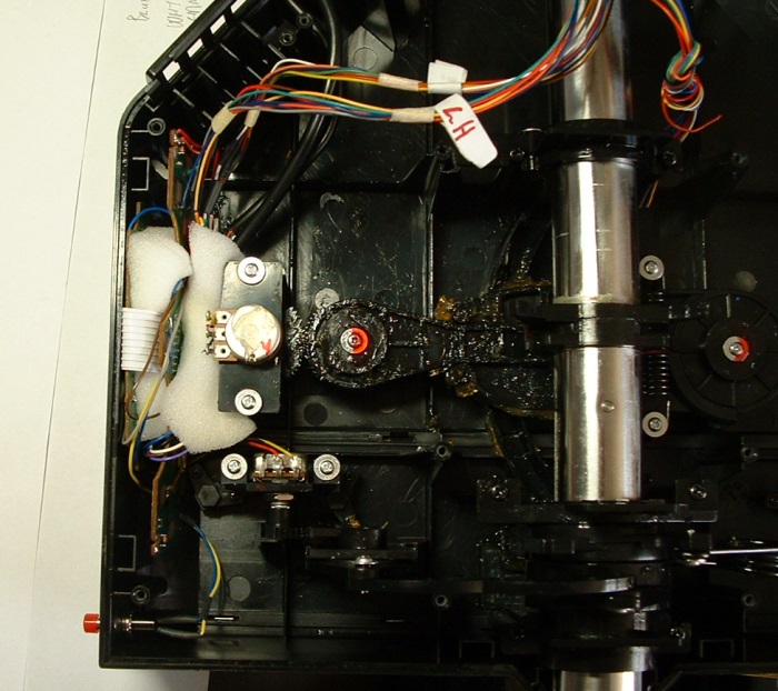
Next, the quadrant lever unit is now useless as is, so with that I opened it up, cut and rewired the throttle and mixture lever pots to position on the controller boards.
Finally, I positioned the board in position, holding it all suitably in place with some foam pieces;
Final thoughts: It works as well as the original but one needs to be sure it is switched to analogue mode - caught me out a couple of times.
And there you go..we're flying again..
Well, I finally got down to it, and thought I would share the "salvage operation" on here for the benefit of others.
(Notice that it is not a repair.)
With the unit totally dead, the logical thing to do is to replace the circuit board with that of another suitable joy stick. This is what I done, as follows:
I found a suitable replacement circuit board to be from a USB games controller.
This unit comes with:
1. two thumb joysticks, each one with an analogue x/y axis, (Aileron and elevator on the one, throttle and mixture on the other one.)
2. A set of dedicated POV buttons, needed also for the Saitek POV. (Point of View)
3. 10 Switches for the hand controls.
(The first test I done was to see whether I could replace the x/y pots directly with the Saitek pots, and found them 100% compatible.
(ie, it calibrates correctly).First thing is to identify the Saitek wire connections. I found that the wires are bundled together in three groups, or looms.
One loom for the Left hand buttons, one loom for the Right hand buttons and one loom for the center clock. (Which we don't need)
Following is the button designated colours. (Colors for our USA friends
The left hand button loom has 8 wires, as follows:
(Common to all the LH switches = Orange)
1. POV Up = Slate (Light grey)
2. POV Down = Blue
3. POV Left = Green
4. POV Right = Dark blue
5. A1 = Red
6. A2 = Brown
7. E = Yellow
8. Common = Orange
The right hand button loom has 9 wires, as follows:
(Common to all the RH switches = Red)
1. B1 = Black
2. B2 = Orange
3. C1 = Yellow
4. C2 = Brown
5. D = White
6. Mode 1 = Slate
7. Mode 2 = Green
8. Mode 3 =Blue
9. Common = Red
Next consideration are the two Saitek pots, X Axis for Alerons, Y Axis for Elevator. See photo:
Next is to prepare the USB controller board: This is the board as removed from the USB unit.
Next I removed the two joy sticks, AND soldered in 5 jumper wires - because connection was previously by the joystick metal bodies.
And now you can see where it is leading, can't you.
The following photo identifies the USB switch positions.
With the exception of the POV wiring and the pots, any of the yoke buttons can really be wired to any of the switches - mapping can be sorted in the FS itself.
But there remains one very important nuisance.
These USB controllers can operate in either "switch" or "Analogue" mode and we need to ALWAYS be in analogue mode.
On starting up, they default to switch mode. To switch to analogue mode, there is a small push button
on the front of the controller, and an LED to indicate. (See the very first photo). Problem is this button needs to be a momentarily switch, meaning it cannot be hard wired.
To overcome this, I installed a small N/O pushbutton switch on the side of the Saitek housing, as well as a 3mm hole for the indicator LED.
The switch is then wired to the board as follows:
Next, the quadrant lever unit is now useless as is, so with that I opened it up, cut and rewired the throttle and mixture lever pots to position on the controller boards.
Finally, I positioned the board in position, holding it all suitably in place with some foam pieces;
Final thoughts: It works as well as the original
And there you go..we're flying again..


 )
)