Cockpit Construction Continued (Part 9)

Only for Genuine FS fanatics! Taking this hobby from Real to Surreal? Or maybe just combining 4 hobbies into 1 ;)

Cockpit Construction Continued (Part 9)

Postby JBaymore » Mon Aug 30, 2004 9:50 pm

More Control Panel Fronts Finished

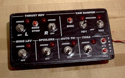
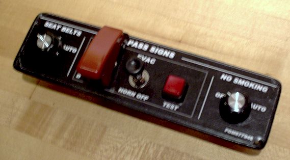
Well...... here are some more panels with the switches, knobs and leds and such mounted.  The designs were documented in the last couple of "parts" of this series.  See the prior threads for other info on these.... not going to say too much more here.  Picture is worth a thousand words amd all that.

Sorry about some being a bit fuzzy.


Image


Image


Image


Image

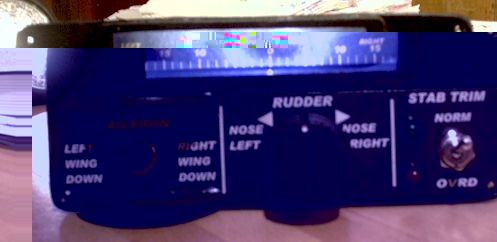
The image above shows the rudder trim control panel.  In the picture I have a flashlight shining thru the indicator gauge location to simulate how it will look with the trim position gauge backlit.  At the moment it is simply a piecve of paper there.... but the milky transparent gauge facing is already completed and is awaiting a bracket to mount it.  The trim knob will move a pointer on the dial facing for an accurate mechanical linkage readout.


Image


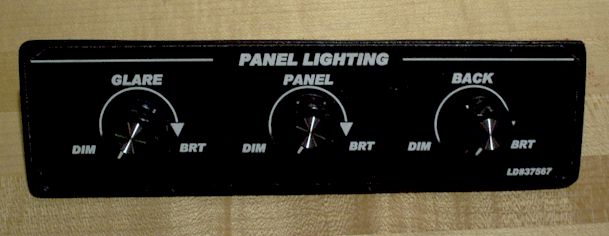
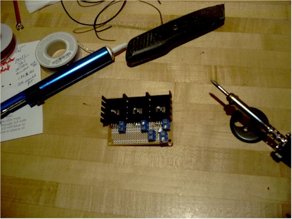
I have just started constructing some of the electronics for the pit.  Below is a small unit to take 12V dc regulated from an old ham radio 8 amp supply I have and convert it to 3 separate 0-5V dc 1 amp variable supplys that will control the dimming of led type panel lights.  This unit hooks to the Dimming Panel with the three knobs which you see above.

Image


best,

........................john
Image ImageIntel i7 960 quad 3.2G LGA 1366, Asus P6X58D Premium, 750W Corsair, 6 gig 1600 DDR3, Spinpoint 1TB 720
User avatar
JBaymore
Global Moderator
Global Moderator
 
Posts: 10020
Joined: Sat May 24, 2003 9:15 am
Location: New Hampshire

Re: Cockpit Construction Continued (Part 9)

Postby SilverFox441 » Sun Sep 05, 2004 2:04 am

JBaymore,

I came up with a Door Lock logic that might appeal to you...

Switches:
  • SW1-Lock Dial
  • SW2-Throttle Cutoff (normally closed)
  • SW2-Throttle Cutoff (normally open)
Throttle switch is set up to make when the throttle is fully in cutoff position.

"Lock" indication...
SW1 in "LOCK" position OR SW1 in "AUTO" AND Throttle not at cutoff (SW2 Normally Closed)

"Unlock" indication...
SW1 in "UNLOCK" position OR SW1 in "AUTO" AND Throttle at cutoff (SW2 Normally Open)

"Fail" indication..
SW1 in "UNLOCK" position AND Throttle not at cutoff (SW2 Normally Closed)

Notice that the door lock is "Engaged" anytime engines running...not just when the gear is up. :)  
Steve (Silver Fox) Daly
User avatar
SilverFox441
Major
Major
 
Posts: 1335
Joined: Sun Apr 13, 2003 12:54 am
Location: Mississauga, Ontario, Canada

Re: Cockpit Construction Continued (Part 9)

Postby Fly2e » Thu Sep 16, 2004 9:50 am

John, where do you get all these custom controls & knobs. Do you have each plate custom made?

I can't wait to see this thing fly!!

Dave
COMING SOON!
User avatar
Fly2e
Colonel
Colonel
 
Posts: 198020
Joined: Thu Jan 17, 2002 5:29 pm
Location: KFRG

Re: Cockpit Construction Continued (Part 9)

Postby JBaymore » Thu Sep 16, 2004 2:21 pm

Dave,

I spent a lot of "design time" working a lot of it out in my head before I ever set saw to particleboard.   I looked at a lot of pictures of real aircarft on places like the Airliners.net site.  I also looked long and hard at what FSUIPC could control.  I looked at the default functions in FS2004.  I looked at the GoFlight stuff.  

And I looked carefully at all the virtual aircraft panels that I flew.

Then I stole what I felt were good ideas from multiple places and assembled them into my "Generic Jet".  I also spent some time in my car and measureing my "reach" to various locations... to decide sizes and positions

I use a computer draw program to compose the panels..... laser print them...... laminate them onto the mdf cutouts with ModPodge...and then drill the holes.  The switches and such get mounted normally.

See the existing threads below....it'll probably give you the info you are looking for.

There is an electronic surplus place near here... 30 minute drive.  About $1 per switch or led unit..... but you take what they have around at the time.  Then there is Radio Shack for the occasional item.  And so on.


http://www.simviation.com/cgi-bin/yabb/YaBB.cgi?board=homebuild;action=display;num=1079431551

http://www.simviation.com/cgi-bin/yabb/YaBB.cgi?board=homebuild;action=display;num=1080500592

http://www.simviation.com/cgi-bin/yabb/YaBB.cgi?board=homebuild;action=display;num=1081104497


best,

........................john
Last edited by JBaymore on Thu Sep 16, 2004 2:37 pm, edited 1 time in total.
Image ImageIntel i7 960 quad 3.2G LGA 1366, Asus P6X58D Premium, 750W Corsair, 6 gig 1600 DDR3, Spinpoint 1TB 720
User avatar
JBaymore
Global Moderator
Global Moderator
 
Posts: 10020
Joined: Sat May 24, 2003 9:15 am
Location: New Hampshire

Re: Cockpit Construction Continued (Part 9)

Postby npbosch » Thu Sep 16, 2004 2:59 pm

Hi John

Well done. I would like to know how you did the mechanically linkage between the rudder trim button and the indicator above.

I have thought a lot about that but didn't find a good solution yet. So an explanation or even better a pic would be much appreciated.

Regards


norbert bosch


http://home.wanadoo.nl/norbert.bosch
User avatar
npbosch
Ground hog
Ground hog
 
Posts: 27
Joined: Sat Dec 20, 2003 6:34 pm

Re: Cockpit Construction Continued (Part 9)

Postby JBaymore » Sat Oct 02, 2004 2:19 pm

Norbert,

First of all... thanks for the kind words!  8)


I will try to get a photo of the rear of the panel soon so that I can show you how it is done.  It helps to be a "mature" individual for the genesis of the linkage idea.....back to my early ham radio days.

best,

................john  
Image ImageIntel i7 960 quad 3.2G LGA 1366, Asus P6X58D Premium, 750W Corsair, 6 gig 1600 DDR3, Spinpoint 1TB 720
User avatar
JBaymore
Global Moderator
Global Moderator
 
Posts: 10020
Joined: Sat May 24, 2003 9:15 am
Location: New Hampshire

Re: Cockpit Construction Continued (Part 9)

Postby JBaymore » Sat Oct 02, 2004 2:22 pm

[quote]JBaymore,

I came up with a Door Lock logic that might appeal to you...

Switches:
  • SW1-Lock Dial
  • SW2-Throttle Cutoff (normally closed)
  • SW2-Throttle Cutoff (normally open)
Throttle switch is set up to make when the throttle is fully in cutoff position.

"Lock" indication...
SW1 in "LOCK" position OR SW1 in "AUTO" AND Throttle not at cutoff (SW2 Normally Closed)

"Unlock" indication...
SW1 in "UNLOCK" position OR SW1 in "AUTO" AND Throttle at cutoff (SW2 Normally Open)

"Fail" indication..
SW1 in "UNLOCK" position AND Throttle not at cutoff (SW2 Normally Closed)

Notice that the door lock is "Engaged" anytime engines running...not just when the gear is up. :)
Image ImageIntel i7 960 quad 3.2G LGA 1366, Asus P6X58D Premium, 750W Corsair, 6 gig 1600 DDR3, Spinpoint 1TB 720
User avatar
JBaymore
Global Moderator
Global Moderator
 
Posts: 10020
Joined: Sat May 24, 2003 9:15 am
Location: New Hampshire


Return to Home Cockpits and Setups

Who is online

Users browsing this forum: No registered users and 476 guests