New Forum Survey: Homebrew Cockpits (see below)

Only for Genuine FS fanatics! Taking this hobby from Real to Surreal? Or maybe just combining 4 hobbies into 1 ;)

Re: New Forum Survey: Homebrew Cockpits (see below

Postby Smoke2much » Thu Oct 02, 2003 6:54 am

John,

In my usual "Heath-Robinson" way of doing things I have discovered the need for a number of cogs to use as reduction gear for trim wheels etc.  I am currently planning to use Lego or Meccano, both of which are relatively cheap and tough - they're built to outlast children after all.  If this does not prove viable can you suggest another source?  I'm out of ideas here, clocks would be far too flimsy.

Will
Who switched the lights off?
User avatar
Smoke2much
Major
Major
 
Posts: 2755
Joined: Sun Jan 05, 2003 6:33 pm
Location: Sittingbourne, Kent,

Re: New Forum Survey: Homebrew Cockpits (see below

Postby JBaymore » Thu Oct 02, 2003 8:33 am

[quote]My main joystick is USB and the rudder pedals are plugged into the game port.
Image ImageIntel i7 960 quad 3.2G LGA 1366, Asus P6X58D Premium, 750W Corsair, 6 gig 1600 DDR3, Spinpoint 1TB 720
User avatar
JBaymore
Global Moderator
Global Moderator
 
Posts: 10020
Joined: Sat May 24, 2003 9:15 am
Location: New Hampshire

Re: New Forum Survey: Homebrew Cockpits (see below

Postby Smoke2much » Thu Oct 02, 2003 9:04 am

I'm having a very pleasant afternoon tinkering with them, in a minute I'm going to go out and get myself a soldering iron and other gubbins from a hardware shop so that I can lengthen the wires and hopefully replace the little switches.

I made an error, I have only four switches(buttons) but the current plan is to use the old y axis pot for elevator trim or throttle.  

Button 1 is landing gear, 2 will be flaps down, 3 flaps up and 4 ATC toggle.

I think I will use the pot for elevator trim as it is surprisingly easy to balance rudders when you use your feet.

The set-up will therefore be:

Controller 1 - Joystick Elevators and Ailerons X+Y axes

Button 1 Brakes
Button 2 Enrich mixture
Button 3 Lean mixture
Button 4 Coarse Prop
Button 5 Finer Prop
Button 6 Knee pad
Button 7 Auto pilot toggle

Throttle slider Throttle

Controller 2

X axis Rudder
Y axis Elevator trim

Button 1 Gear
Button 2 + 3 Flaps
Button 4 ATC Toggle.

This is by no means a homebrew cockpit but it is a start.  I have a thrustmaster joy pad with ten buttons and 4 pots which I plan to cannabalise for parts, I also have an old keyboard somewhere that will give me a further 60 odd available buttons for a "flight console".

I'll take photo's and keep you updated.  

The next step is to build a control yoke and throttle quadrant like yours as these are all things that can be stored in boxes in the attic and brought out whenever I wish to use them, space constraints you understand.

Will
Who switched the lights off?
User avatar
Smoke2much
Major
Major
 
Posts: 2755
Joined: Sun Jan 05, 2003 6:33 pm
Location: Sittingbourne, Kent,

Re: New Forum Survey: Homebrew Cockpits (see below

Postby JBaymore » Thu Oct 02, 2003 12:42 pm

Oh...... and if you are a "GUEST" here on SimV and are reading this thread..........

Please join SimV.  It is not hard.... and there's a lot of great people here and lots of useful information.

And then you can "chime in" on this thread too.  ;)

best,

.................john
Image ImageIntel i7 960 quad 3.2G LGA 1366, Asus P6X58D Premium, 750W Corsair, 6 gig 1600 DDR3, Spinpoint 1TB 720
User avatar
JBaymore
Global Moderator
Global Moderator
 
Posts: 10020
Joined: Sat May 24, 2003 9:15 am
Location: New Hampshire

Re: New Forum Survey: Homebrew Cockpits (see below

Postby JBaymore » Thu Oct 02, 2003 9:33 pm

Ripping Into an Axispad FX Joypad  -(corrected)-


(See prior posts in this thread to understand what this unit will be used for.)

I took a few minutes today and started ripping apart the Axispad FX gamepad for conversion to part of a simulated cockpit setup.
Image ImageIntel i7 960 quad 3.2G LGA 1366, Asus P6X58D Premium, 750W Corsair, 6 gig 1600 DDR3, Spinpoint 1TB 720
User avatar
JBaymore
Global Moderator
Global Moderator
 
Posts: 10020
Joined: Sat May 24, 2003 9:15 am
Location: New Hampshire

Re: New Forum Survey: Homebrew Cockpits (see below

Postby JBaymore » Sat Oct 04, 2003 12:56 pm

1st Revision of Throttle Quadrant Layout

In learning from looking at the FS2004 "Axis Assignments" that both the flaps and the spoilers can have infinite potentiometer control mapping......... I decided to add the spoiler control to my throttle quadrant.  So that put another angled lever arm to the left of the four throttle levers..... bringing the total levers to six.

I also did not like the way the tension on the resistance to movement for all the levers worked in the older setup.  Too difficult and fussy to set each control individually.  So I changed to using some nylon bushings and then will compress the whole assembly from the sides using 1/2" nuts on the 1/2" threaded rod "shaft".  No individual lever control of tension.... but much simpler.

The "mount" to hold the shaft is simply a piece of metal from a joist hanger bent into shape and drilled to accept the 1/2" threaded rod "shaft" at 1" height above the bottom of the box.  The lever arms themselves are cut from stock shelf brackets that fit into wall mounted strips with slots.  Two cuts for length and drill two holes and they were done  ;).

The annotations on the drawing should help you figure out what the various parts are a bit.

Image


One thing that I have to decide here soon is if I will actually "waste" an available channel of "joystick axis" (potentiometer control) from one of the AxispadFX gamepads on the spoilers.  I can also set the spoiler arm lever to just hit a microswitch at the "Arm" point, and another at the "Deploy" point...... and have that just emulate the keyboard presses.  Any thoughts on the subject of having infinitely variable spoilers versus just a "one press = full deploy" type?


best,

..............john
Image ImageIntel i7 960 quad 3.2G LGA 1366, Asus P6X58D Premium, 750W Corsair, 6 gig 1600 DDR3, Spinpoint 1TB 720
User avatar
JBaymore
Global Moderator
Global Moderator
 
Posts: 10020
Joined: Sat May 24, 2003 9:15 am
Location: New Hampshire

Re: New Forum Survey: Homebrew Cockpits (see below

Postby Smoke2much » Sun Oct 05, 2003 4:20 pm

I guess it depends on how much you use your spoliers John.  It's your design after all.  If you have a USB splitter you could use the pots for every available function by sacrificing two or three game pads.

Will
Who switched the lights off?
User avatar
Smoke2much
Major
Major
 
Posts: 2755
Joined: Sun Jan 05, 2003 6:33 pm
Location: Sittingbourne, Kent,

Re: New Forum Survey: Homebrew Cockpits (see below

Postby JBaymore » Mon Oct 06, 2003 8:44 am

Ripping into an Axispad FX -update

Well I got a couple of 10K rotary potentiometers.
Last edited by JBaymore on Mon Oct 06, 2003 8:46 am, edited 1 time in total.
Image ImageIntel i7 960 quad 3.2G LGA 1366, Asus P6X58D Premium, 750W Corsair, 6 gig 1600 DDR3, Spinpoint 1TB 720
User avatar
JBaymore
Global Moderator
Global Moderator
 
Posts: 10020
Joined: Sat May 24, 2003 9:15 am
Location: New Hampshire

Re: New Forum Survey: Homebrew Cockpits (see below

Postby JBaymore » Mon Oct 06, 2003 9:02 am

Will,

Hi.

I really don't understand the full use of a "variable spoiler" for flight yet.
Last edited by JBaymore on Mon Oct 06, 2003 9:05 am, edited 1 time in total.
Image ImageIntel i7 960 quad 3.2G LGA 1366, Asus P6X58D Premium, 750W Corsair, 6 gig 1600 DDR3, Spinpoint 1TB 720
User avatar
JBaymore
Global Moderator
Global Moderator
 
Posts: 10020
Joined: Sat May 24, 2003 9:15 am
Location: New Hampshire

Re: New Forum Survey: Homebrew Cockpits (see below

Postby Smoke2much » Mon Oct 06, 2003 9:53 pm

Maybe the only reason for M$ giving the option for an axis is that it has three available settings rather than 2.
Last edited by Smoke2much on Mon Oct 06, 2003 9:54 pm, edited 1 time in total.
Who switched the lights off?
User avatar
Smoke2much
Major
Major
 
Posts: 2755
Joined: Sun Jan 05, 2003 6:33 pm
Location: Sittingbourne, Kent,

Re: New Forum Survey: Homebrew Cockpits (see below

Postby JBaymore » Tue Oct 07, 2003 9:24 am

Copy of related topic post from "Hardware" section

Is there a way to link 2 identicle sticks, 2 throttles and 2 sets of rudder pedals to the same pc to create a co-pilot position for a cockpit project, or would I have to network the two positions with 2 PCs?  This is probably a dumb question. Thanx


BaileyGirl,

Hi and welcome to SimV.

I am working on a simulated cockpit project also.

The answer is yes..... with some "possibly difficult to construct"  caveats.

In a real world dual setup the physical movements of both the rudder pedals and the yoke would be "mirrored" to the other position.  If the captain turned the yoke to the right.... the first officers yoke would also pivot to the right.  Pitch down on one and the other moves forward too.  To model this type of exact behavior requires a lot of either mechanical linkage or servomotors to be driving things.

Constructing a mechanical yoke system is not all that difficult if you are handy with tools and mechanical design.......... just kinda "fussy" and time consuming and likely a bit on the "pricey side" when all is said and done.  There are a couple of companies that sell such "real" looking and functioning large jet yokes..... but unless you are willing to go about $600 per station......... you'd best be thinking of how to do it yourself.

Cable linkages under the raised floor of the simulated cockpit are the usual route for this setup.  Gets into a bunch of pulleys and gears and it translates the movement of both sticks into the movement of just a set of two linear or slide potentiometers (like volume controls) that are interfaced into the sim the same way a joystick is.  In fact you can canibalize a joystick for the interface card electronics and then just re-use the potentiometers in a new location if your design matches.  Or use different potentiometers (also called "pots") that are of the same resistance value.

If you just want "dual controls" and can do without the matching motion feedback part of things ......... you can just connect two USB joysticks, for example.  Whichever one is "touched" in any way (moved) then suddenly takes flight control priority.  Ditto throttle controlls, and ditto pedals.  Any USB controller tends to work this way.

The problem with this setup, aside from the lack of motion feedback, is that when the second control is
moved, then whatever "setting" the first control was at is suddenly overridden.  This can result in some really jerky transitions of control.  For examople if the throttle at the captain's position was at 90 percent.... and then the co-pilot touched the throttle at his/her side and it was initially starting at an idle setting..... the engines would, for an instant, drop from 90 percent to idle...and then spool back up to whatever setting the co-pilot then had set.

Since you are interested in "Simulated Homebrew Cockpits" you might want to go down to the "General" Section of the forums and check out the thread there that is about this very subject.  It is possible that a forum section for this exact subject may get set up if there is enough demonstrated interest.  Please vote in the little "survey" if you haven't already.

There is a picture or two down there of the ongoing construction of my new throttle quadrant.  It might give you some ideas. It is not including servomotor feedback so that things like autothrottle will itself move the position of the throttles.... although that is doable (requires some expensive electronics starting with an EPIC interface card).  It is set up to control four engines, spoilers, and flaps.

I am posting a copy of this message down in that thread also...... to keep the "cockpit topic" running all together in one place at least for now ..........until we see if "the powers that be" will grant forum status to this concept.

Welcome to the "oddball" world of building a home simulator  ;).


best,

....................john
Image ImageIntel i7 960 quad 3.2G LGA 1366, Asus P6X58D Premium, 750W Corsair, 6 gig 1600 DDR3, Spinpoint 1TB 720
User avatar
JBaymore
Global Moderator
Global Moderator
 
Posts: 10020
Joined: Sat May 24, 2003 9:15 am
Location: New Hampshire

Re: New Forum Survey: Homebrew Cockpits (see below

Postby JBaymore » Tue Oct 07, 2003 2:17 pm

Interesting Video Display Possibility

Found this when researching display possibilities for a wider view in the simulated cockpit:

http://www.panoramtech.com/products/pv230.html

No listing of the PRICE though.

It looks awesome for simming  :o .  It already sort of looks like looking out the front three windows of a cockpit of some sort.  Easy to visualize building a simulated cockpit around it.


best,

..........john
Image ImageIntel i7 960 quad 3.2G LGA 1366, Asus P6X58D Premium, 750W Corsair, 6 gig 1600 DDR3, Spinpoint 1TB 720
User avatar
JBaymore
Global Moderator
Global Moderator
 
Posts: 10020
Joined: Sat May 24, 2003 9:15 am
Location: New Hampshire

Re: New Forum Survey: Homebrew Cockpits (see below

Postby JBaymore » Tue Oct 07, 2003 9:15 pm

Ripping Into An AxisPad FX Gamepad

I am continuing working on using the Axispad FX gamepad as the basis for a USB "interface card" to utilize the multiple buttons and the double joysticks it contains for mapping to other functions.  (See earlier posts in this thread.)

I now have all the wiring connections soldered in place on the gamepad circuitboard itself.  The next step is to mount the Axispad circuit board onto another piece of perf board for stability, and then to hook the various wires onto connectors that will serve to easily hook up the controls that will be located in the simulated cockpit.

Mechanically these "surface solder connections" are NOT the best and most stable way to connect things.  But this circuit board is double sided ...so drilling a little hole at each solder location is not possible.  So getting the whole thing as rigid as possible as soon as possible is a good idea.

Here in photo #1 is the Axispad FX with the top cover removed before I have done too much to it.  On the right side, the rubberized plastic button covers have been removed showing the copper trace contacts that the conductive material that is on the back side of the rubberized button sheet makes contact with.  It is onto these traces that you need to solder new wires to remote the closure connection out to other buttons located on your panels.

I am not sure what I will be doing with the outputs for the two force feedback vibration motors.  Their use intrigues me.... and I may see what can be done with them.  I have to figure out what command in the sim would cause them to activate.  I expect it will be in the aircraft.cfg file under the force feedback section...... but I don't know anything about that yet.  Any thoughts anyone  ???.  More on that research MUCH later.


Photo #1
Image


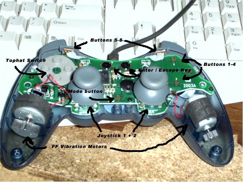
Here below in photo #2 is more of a close-up of the circuit board before I have added new wiring.  The left joystick is already removed.  You can see that some of the switch traces have contacts that are pretty simple to solder onto..... big flat planes of polished copper.  Some however... like buttons 1-4 in the upper right and also the "mode button" in the center bottom...... have little tiny "fingers" of copper traces that intermesh.  These take some really careful work.  On some of them I used an exacto knife and cut some of the "fingers" to make the soldering easier to do.

Some of the buttons activate by bringing the hot side to "ground".  So for these buttons you only need one lead.... and use a common "ground" connection for the other lead.  So that is why you don't see "pairs" of leads coming off each button point on the circuit board.  Some buttons do NOT work this way so they have two leads.  The top hat buttons are like this.... and each "pair" of buttons has a separate second lead.  So if you look close at the last picture, you'll see four red wires on the tophat button section....and only two black wires.

Buttons number 9 and 10 (not seen) seem to have four contact points on the pc board...... but in reality only two of them for each switch are actually connected to anything if you study the traces.  If you look at the last picture... you can clearly see the two wires connected at the diagonal corners of button number 9's position.

On the pot connections where the joysticks used to be, the two end holes on the pc board of each set of three holes see the full 10K ohm constant resistance of the potentiometer.  The center hole is where the variable resistance is "read".  The color coding on the pots is red, black, green wires.....with the black being the center variable connection.


Photo #2
Image


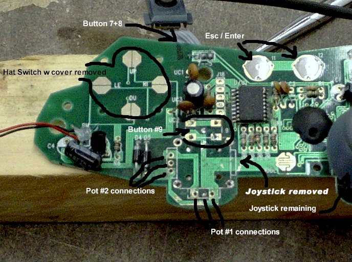
In this last shot all of the added wiring in now soldered into place.  The wires are sort of now grouped into four "sections".  The top left and right are bundles of what will be various control buttons.  The lower left is the two axis connections for one joystick ....which are now really just "analog inputs" onto which I can now attach 10 K potentiometers.  The lower right side is the two axis connections for the other joystick.

In the center bottom is the switch connection for the "mode" button.  The Axispad needs to be set to the analog mode to activate the joysticks.  Haven't figured out how to "bypass" this needed keypress.  So that button will have to be on the "checklist"  ;).  At the top are two buttons for "Escape" and "Enter".  At the moment I don't plan to use them so no wires are soldered onto them.  The USB connector that already came on the gamepad is located in the center top.

You'll also notice that the contact covers on the "enter" and "escape" buttons have been removed in the last picture.  So now they are not really push button switches anymore.  Now they are just little "bullseye" circuit board traces.


Photo #3
Image


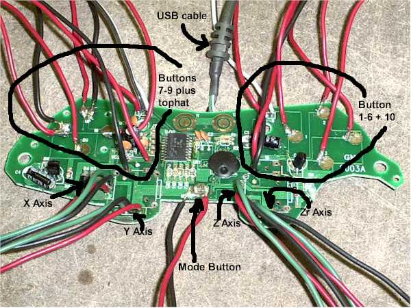
So canibalizing one Axispad FX gamepad gets you 14 buttons and four joystick 10K analog inputs to locate onto a simulated cockpit.

So there you have an update on my work on this conversion so far.  Hopefully these pictures will be useful if you are planning on trying this modification too....or even one sort of like it.  

I'll keep this info coming as it develops.  I'm having fun  so far ;D.


best,

.................john
Image ImageIntel i7 960 quad 3.2G LGA 1366, Asus P6X58D Premium, 750W Corsair, 6 gig 1600 DDR3, Spinpoint 1TB 720
User avatar
JBaymore
Global Moderator
Global Moderator
 
Posts: 10020
Joined: Sat May 24, 2003 9:15 am
Location: New Hampshire

Re: New Forum Survey: Homebrew Cockpits (see below

Postby bailey_girl » Wed Oct 08, 2003 1:27 am

 simpits.org is an organization with a website and web ring dedicated to homebrew cockpits.  I have been researching such a project for 2 years now, changed my plans about 4 times, began building this summer, scratched the idea and changed my design again.  From my research I can tell you that the community of home cockpit builders seeking more immersion in their flight sims is very talented and rapidly growing in numbers.
This would be a great forum subject. This thread already has more replies than any cockpit forum I have researched, including the long-running simpits.org.
 Not many people know about simpits.org and other similar websites, but Simviation.com is very popular and
has the ability to spawn a very successful forum and information base for this topic.
User avatar
bailey_girl
Ground hog
Ground hog
 
Posts: 21
Joined: Mon Aug 18, 2003 11:14 pm
Location: Minnesota, USA

Re: New Forum Survey: Homebrew Cockpits (see below

Postby Smoke2much » Wed Oct 08, 2003 1:30 am

Thanks for the input.  I for one will look into this site/ring you mention.  All my plans are on hold at the moment due to a nasty stretch of night shifts. :(

Will
Who switched the lights off?
User avatar
Smoke2much
Major
Major
 
Posts: 2755
Joined: Sun Jan 05, 2003 6:33 pm
Location: Sittingbourne, Kent,

PreviousNext

Return to Home Cockpits and Setups

Who is online

Users browsing this forum: No registered users and 91 guests